Home Blog Page 115

Maintaining the 385s

In December, ScotRail accepted into service the last of the 70 Class 385 EMUs that Abellio had ordered from Hitachi in a £475 million contract. This was signed in April 2015, just before the company took over the ScotRail franchise.

The completion of this order, together with the introduction of HSTs on Scottish intercity routes, brings the number of passenger coaches operated by ScotRail to 1,016, an increase of 28 per cent since the start of the Abellio franchise. These extra vehicles have enabled ScotRail to use the diesel multiple units (DMUs) they replace to strengthen services and to withdraw its Class 314 EMU fleet that was built in the late 1970s.

Two 4-car class 385 units on a Glasgow to Edinburgh service.

ScotRail’s Class 385 fleet comprises 46 three-car and 24 four-car units. These operate services between Edinburgh and Glasgow via Falkirk High, Cumbernauld and Shotts as well as the Dunblane/Alloa, North Berwick/Dunbar, Lanark and Cathcart circles services. The manufacture of the Class 385s and their introduction into service is described in issues 157 (November 2017) and 162 (April 2018).

Under the contract, the first train was to be operational in Autumn 2017, with all trains on the main Edinburgh to Glasgow line via Falkirk High operated by Class 385s from December 2017. However, for various reasons, including a much-publicised windscreen problem, the first unit did not enter service until July 2018. Since then the number of diagrams worked by the units were: November 2018 – 10; December 2018 – 32; May 2019 – 58 and after the December 2019 timetable change – 62.

This new timetable also saw the widespread use of eight-coach trains on the Edinburgh to Glasgow main line, which was made possible by platform extensions at Glasgow Queen Street station. The eight-coach Class 385 trains have 546 seats. This is 45 per cent more seats than the six-coach Class 170 DMUs that operated this service before the line was electrified.

At the time of writing, ScotRail’s Class 385 fleet has accumulated 8.5 million miles running. The fleet ran 727,000 miles in just one four-week period before Christmas.

Hitachi’s Glasgow central planning contract office.

The contract between Hitachi and Abellio also included a 10-year contract for the maintenance of these units. This is managed at Hitachi’s central planning contract office in Glasgow and undertaken at the company’s Craigentinny train maintenance centre, which also does maintenance work on LNER’s Azuma fleet. Whilst it is not unusual for new train contracts to include maintenance agreements, this is the first time that ScotRail has relied on another company to maintain its trains. Furthermore, as is the case with all new trains, the Class 385s have numerous sensors and are software controlled.

For these reasons Rail Engineer was glad of the opportunity to visit both Hitachi’s Glasgow office and its Craigentinny depot to see how the class 385 units are maintained.

Host for these visits was Tim Olton, Hitachi’s general manager for Scotland, who advised that the company established itself in Scotland in April 2016 and now has 300 people supporting its Scottish train operations, of which around 40 are based in Glasgow and across Scotland’s central belt. Tim explained that the central planning contract office was essential to maintain close contact with ScotRail’s head office for there to be effective collaboration in the delivery of the train service agreement.

Hitachi Glasgow

Our tour started at the Glasgow office. Here we meet Stephen Williams, who is responsible for control room and outstations, and Craig Morrison, the fleet performance and planning manager responsible for the central planning cell. Reporting to Stephen are six maintenance controllers and 25 riding inspectors.

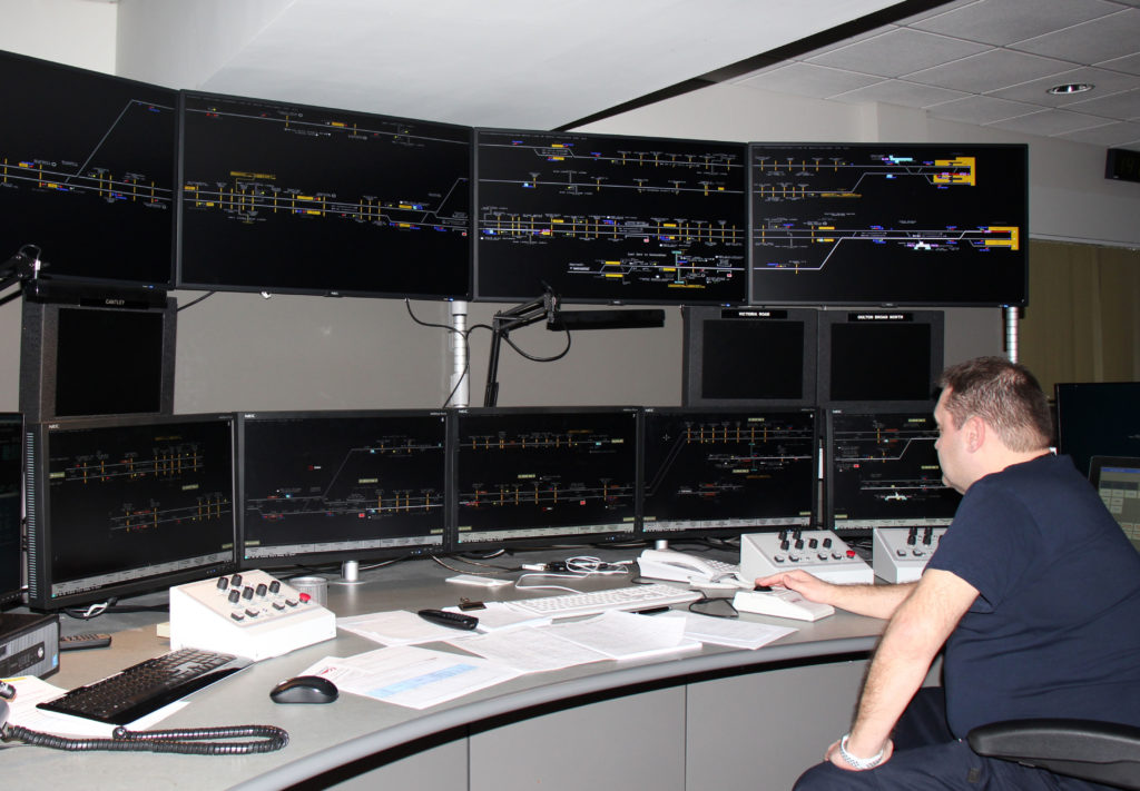
The maintenance controllers are co-located with ScotRail’s maintenance control in the West of Scotland signalling centre at Springburn, close to Glasgow city centre. They can speak directly to the train crews, resolving any issues as quickly as possible in order to limit delays to the service. The 25 riding inspectors check the trains in service and undertake repairs around the clock at ScotRail’s berthing locations.

Craig has a team of six fleet planners who plan maintenance examinations, fleet checks and modifications at Craigentinny depot and ScotRail’s berthing locations. He also has two contract performance technicians who manage delay attribution and fleet performance, including the management of in-service defects and the monitoring of repeat defects.

The work of the Glasgow office is supported by two key systems – SOROS and HFMT. SOROS is a web-based fleet maintenance planning tool, designed to optimise control and coordination of operations, maintenance and safety management activities, developed by Danburykline.

Class 385 and HST at Craigentinny.

The Hitachi Fleet Monitoring Tool (HFMT) uses condition and fault information data transmitted from the train management system (TMS). This is an autonomous, decentralised, integrated system that has a 100-Mbit/s ethernet backbone and controls traction, braking, passenger information and air conditioning, as well as providing functions such as selective door opening and driver advisory systems. It is designed to reduce the amount of wiring, consolidate on board equipment and provide extensive fault detection and automatic testing.

The information obtained from the HFMT is used to proactively manage performance of the fleet by providing real-time information on system health and notification of train faults. It also provides remote fault finding and defect analysis. As an example, this ensures that units with incipient faults are not unnecessarily removed from service. This is possible as HFMT provides information about such things as gearbox oil levels and water tank levels. It also sends an alert in certain situations such as an emergency brake application and the activation of a pantograph automatic dropping device.

Relevant information from HFMT is also passed on to Network Rail. This includes adhesion hot spots, as indication from frequent wheel slide protection activation, and OLE over-voltage.

Weekly meetings are held with drivers and train crew to provide them with advice and information about technical incidents. Tim advised that the rapport that has developed between the technical riding technicians and train crew has proved particularly useful by, for example, reducing the number of coupling/uncoupling incidents.

Craigentinny

Hitachi took over the operation of Craigentinny depot from LNER in November 2018. At the time, the depot had its full fleet of LNER’s 15 diesel HSTs to maintain and also serviced the company’s IC225 trainsets as well as the occasional Hitachi-built Azuma, which had not yet entered service.

The depot also had contracts to maintain Voyager units for CrossCountry trains, Class 73 locomotives for Caledonian Sleeper and Class 350 EMUs for TransPennine Express. It had also started to maintain Class 385 units, of which about 30 were in service at this time. The variety of work undertaken by the depot is explained in issue 139 (May 2016).

At the time of my visit, the depot was about to lose its last HSTs. Two sets had been rebranded, ready to be sent to East Midlands Railway, and two power cars had been repainted in British Rail colours ready for their last LNER passenger service, a four-day “Let’s go around again” farewell special.

With almost half LNER’s Azuma fleet operational, the depot also had an increasing number of Class 800/801s to service. Another change was that it was also about to lose its TransPennine Class 350 units, although the depot was just starting to maintain the new Nova 1 units which are Hitachi-built Class 802s. These units operate a new TransPennine service on the East Coast main line from Edinburgh and Newcastle.

Tim advised that one result of all these changes was that, other than some Class 73 maintenance, the depot no longer maintains HST power cars and locomotives. As a result, much of the depot repair shop space where this work was done is now not required. This provided an opportunity to establish a new technical training facility for the Hitachi-built Class 385, 800, 801 and 802 units, which share many common components.

Transpennine Nova 1 unit at Craigentinny.

Class 385 maintenance

Class 385 engineering manager, Alasdair MacPherson, advised that the depot has 270 skilled maintenance engineers and fitters who are all qualified to work on every fleet. He considers that the Class 385s are a great step forward from the Voyagers and Class 350s even though the new ScotRail units require a different approach – the first step when fault finding is to plug in a laptop.

The training required an integration overview with modules for every system including the TMS, doors and toilets. For a technician with no railway experience, around six months training is required.

385 007 undergoes an X13 examination at Craigentinny. The roof access platform was built to enable Class 385s to be maintained at the depot.

Alasdair advised that Class 385 maintenance is undertaken by a balanced examination system which ensures the amount of work in each examination is about the same. This requires an examination to be undertaken every 20,000 miles or 40 days, whichever comes first. These exams are denoted XN where N is the exam sequence number. The last examination is X36.

Given the amount of information available from the TMS, we discussed the feasibility of introducing a condition-based monitoring maintenance regime rather than the conventional fixed examinations. Tim commented that Hitachi is open to this idea and that TMS data is being used to review maintenance intervals. However, for now, the emphasis is on using tried and tested techniques to ensure reliability. Alasdair makes the point that train component maintenance periodicities will always be a compromise, as the work has to be done when the train is in a depot. Furthermore, any changes to the maintenance regime must be approved in accordance with the ROGS regulations (Railways and Other Guided Transport Systems (Safety) Regulations 2006, updated 2011 and 2013).

At the Millerhill servicing depot, there is a condition monitoring station supplied by MRX Technologies which is due to be commissioned in January. When this is operational, it will enable the Glasgow project office to further refine its maintenance plans with information the monitoring station provides on the wear of pantograph carbons, brake and disc pads as well as wheel profiles.

Improving reliability

The bathtub curve shows the reliability of a fleet throughout its life and identifies three stages of failure: infant, constant and wear out. During the Class 385’s infant failure stage, there had been initial problems with the units involving the TMS, brakes, door setup and speed control unit, all of which have been largely resolved, mainly through software fixes.

TMS updates can be done within a couple of hours at most. These do not require units to come to Craigentinny as technicians can do this at stabling points. However, the speed control unit had to be returned to the manufacturer for its software update.

Alasdair explained that maintenance challenges include evening out the maintenance workload as the fleet is introduced and understanding the intricacies of the IFE electric door system.

MRX monitoring station at Millerhill depot.

Another problem is the different mileages accumulated by the three-car and four-car fleets. This is because the four-car units are primarily used on the main Edinburgh to Glasgow expresses where, each hour, they shuttle between the two cities. Prior to December, this service was a seven-car consist (a three and a four car-unit). However, as many of the three-car unit diagrams are also on lower-mileage stopping services, the three-car fleet has a lower mileage. At the time of my visit, the respective average mileage of the three and four car units was 306 and 572 miles per day.

This mileage disparity increased with the December timetable, which saw the Edinburgh to Glasgow service primarily formed of two four-car Class 385 units coupled together to form an eight-car train.

During my visit, there were six units out of service: two were having X6 and X13 examinations, three needed tyre-turning and one was at Edinburgh Waverley with a TMS fault. In period 10, the Class 385 fleet achieved a record 89,438 miles per technical incident (MTIN) compared with 60,160 in the previous period. As Alasdair pointed out, “the top end of the bathtub curve has now bottomed out”.

Expansion begins at 40

A fortieth birthday is always something to celebrate. It’s a milestone, whether it’s for a person, a company or a product. In this case, it’s a product. The company, Walter Somers Material Handling, was formed in 1953, but it wasn’t until 1980 that the firm, by then known as SomersHandling, introduced its first mobile column lift – the model RG with a lifting capacity of 4,000 to 6,500kg.

That same company, now named Totalkare to reflect its dedication to aftermarket service as well as its high-quality product portfolio, is still supplying mobile column lifts to the commercial vehicle market as well as now supplying railway depots.

To celebrate the birthday of its lifting-jack business, Totalkare is giving itself a birthday present, by investing £750,000 into the business and pressing the button on a five-year expansion plan that will see it target more business in the rail sector.

Planning ahead

“It is the right time to lay the foundations for our next four decades,” explained David Hall, who joined Totalkare just 18 months ago, leading a management buy-out of the Halesowen-based firm.

In that short space of time, the likeable Midlander has overseen a 25 per cent increase in sales and the introduction of new testing solutions into the product portfolio for the first time ever.

“The business will always be based on the founding principles of customer care and being experts in our field and we wanted to build on this philosophy by putting a marker in the sand for the next stage of our development.

“We have already started the process of implementing a new ERP (enterprise resource planning) system that will give us lots of internal and external efficiency improvements and this will pave the way for our relocation to a new purpose built-site in the Midlands. There is also investment being channelled into enhanced service management software to further improve our service capabilities.”

The lifting and testing specialist, who has been involved in the sector for more than 25 years, continued: “In total, this is a significant spend for us and we are in the final stages of negotiations on a great location that is close to our current home in Halesowen.

“It’s a necessary move to give us the ability to optimise the workflow on the shop floor and increase our capacity to hold stock of mobile column lifts, railway lifting jacks and new testing products.”

Excellent reputation

The company is respected throughout the UK for being an industry-leader in the supply, service and maintenance of two and four post lifts, mobile column lifts and forklifter ramp systems. Many of its clients have benefitted from its lifting solutions for 40 years, a customer base that covers some of the biggest names in the bus and coach, commercial vehicle and heavy haulage sectors.

Last year, Totalkare signed a deal with Italy-based manufacturer Emanuel to supply a range of railway lifting jacks with capacities up to 50,000kg that also conform to Machine Directive 2006/42/CE and European standard EN1493. Easily customised, they can be used to lift any rolling stock – from wagons and carriages through to complete trains – providing a safe, flexible and comfortable position for operatives to carry out maintenance, repairs and servicing.

David explained: “We have been working with Emanuel for five years, supplying its heavy-duty four-post lifts into the bus and coach and commercial-vehicle sectors.

“Following a number of conversations, we saw the opportunity to take its manufacturing expertise into the rail sector, where they have similar requirements to provide a safe and fast means of keeping rolling stock operational.”

David Hall.

David, who is joined by Mike Lord, James Radford and Peter Geobey in the new-look leadership team, continued: “There’s a reason our customers have been with us for many years and that stems from the quality of the product and this flows through the aftercare experience.

“We really do care, a mentality that you would normally find in a family-run business. This makes a real difference and we have built on this culture by investing in new technology and by strengthening our service offer with additional engineers now operating all over the country, ably supported by product specialists. The plan is to continue our recruitment drive to grow this team by an additional 20 per cent over the next 12 months.

“It’s a full lifecycle from purchasing the Totalkare product and regular servicing to preventative maintenance, planned refurbishment and swift repairs to ensure we minimise workshop downtime.”

Global connections

Hitachi Rail, a fully integrated, global provider of rail solutions across rolling stock, signalling services and turnkey solutions, is the latest company to benefit from the Totalkare experience. Its assembly plant at Newton Aycliffe, Co Durham, employs 700 people and has recently introduced eight new 15,000kg railway lifting jacks  that will give it flexibility for future projects.

Initially, the jacks will be used to lift metro-style carriages during the manufacturing process.

“We’ve manufactured these lifting jacks in line with Hitachi Rail’s bespoke requirements, with specific attention paid towards the size of the outriggers, height of the anvil and the lifting capacity of each product,” explained area sales manager Adam Bowser.

“This install will be supported through our comprehensive Afterkare service package, which includes two visits per year.”

Wayne Abbott, manufacturing engineer for Hitachi Rail, commented: “We have an existing relationship with Totalkare’s European manufacturing partner Emanuel, having previously used their lifting jacks in Italy.

“Totalkare was the only supplier who could tailor a solution specifically to our requirement and we’re keen to make the most of the additional flexibility it will provide at our Newton Aycliffe facility.”

Moving forward

With numerous birthday celebrations planned for 2020, it’s only right to give David Hall the final word on what the year has in store for Totalkare.

“Like I said before, it’s about laying foundations for the next five years, but that doesn’t mean we haven’t set ourselves ambitious targets. 25 per cent growth is expected again over the next twelve months.

“Personally, I’m really keen to push our online training platform more and increase adoption of technology that can make our workshops safer and help to minimise the number of accidents.

“R&D continues at pace and we are already planning the introduction of another new range of products and increasing the capabilities of our existing ones. We’ve got to stay ahead of the competition – great products with excellent service, that’s the Totalkare way.”

Zero Carbon? Not here! Carbon-fibre bogie frame

During the IMechE’s Railway Challenge in 2019, the judges were hugely impressed with the composite bogie and springs demonstrated on the Poznan University of Technology’s 10¼-inch locomotive. They were so impressed that they awarded a special certificate for this innovation (Issue 177).

Roll on eight months and your writer was attending the 16th annual Vehicle/Track System Interface Committee seminar where Professor Gerard Fernando from the University of Birmingham presented his team’s work on a carbon-fibre bogie. Prof Fernando is Professor of Polymer Engineering and head of the sensors and composites group in the University’s School of Metallurgy and Materials. His collaborators included Dr Tom Sun and Mr Tao Ma.

This was no miniature bogie, but a full size one based on the design of the Alstom bogie used on the class 180 diesel-mechanical multiple unit. The aim of the project is to demonstrate a prototype that can withstand the rigours of 125mph operation with a life similar to a steel bogie and with much less mass.

It is an RSSB-funded collaborative project involving ELG Carbon Fibre, Magma Structures, Alstom and the University of Birmingham. The ‘HAROLD’ full size test rig at the University of Huddersfield (issue 145) will be employed for testing.

The bogie frame – a typical H section – was designed and manufactured by Magma Structures in collaboration with the RSSB and other members of the consortium.  It was constructed out of new and recycled carbon fibres in a fire-retardant epoxy resin (supplied and developed by Gurit).  The robotic build techniques used will also help to reduce mass manufacturing costs.

The design was constrained by the geometry of the existing class 180 bogie and, in order to manage the attachment and reuse of identical existing equipment, the primary brackets were fabricated in steel to interface exactly with the Alstom-supplied existing major components (radial arms, damper brackets, primary and secondary spring systems).  The composite used in the construction has been tested to the requirements of the Euronorm for rolling stock fire safety, EN45545-2, at Hazard level 2 although, in fact, achieved a higher level 3.  The former is the usual requirement for mainline operation.

A major achievement is that the mass of the frame as built is 350kg, compared to the steel equivalent of 936kg.  By the time the metal fittings were installed and paint applied, the mass had increased to 940kg compared with the steel equivalent of 1468kg, a reduction of over half a tonne per bogie.

Gerard explained that the use of the metal components simplified the interfacing with the existing bogie equipment and the carbody, but a bogie designed with carbon fibre construction in mind would be even lighter and would use much less steel.

Optical fibres, sensors and sensing.

Quite unexpectedly in a vehicle-track interface seminar, Gerard turned to the science of using optical fibres as strain and temperature gauges; these being the sensors used for testing the carbon fibre bogie, in addition to conventional surface-mounted electrical-resistance strain gauges.

He explained how an optical fibre 125 micrometres in diameter (250 micrometres with a coating) can be used for this purpose. In very simple terms, a fibre is modified to create Fibre Bragg Gratings (FBG) in the fibre, effectively creating a number of semi-reflective mirrors over short but equal intervals – itself a highly technical process.

When light is shone through a Fibre Bragg Grating, part of the signal is reflected, a small amount of the signal at each semi-reflective mirror (see below). The original reflected wavelengths (without the influence of strain) from each Bragg grating are compared with the reflected wavelengths when the structure is loaded. If the Fibre Bragg Grating is subject to strain, the spacing between the semi-reflective mirrors is either slightly increased (tension) or reduced (compression). This change, combined with the effective refractive index and the period of the FBG, results in a shift in the reflected central Bragg wavelength.

The size of the wavelength change indicates the magnitude of the strain. However, the same effect occurs with change of temperature and temperature effect is over 10 times the strain effect, so a method is required to correct for temperature.

Gerard described the methods used to compensate for temperature where the Bragg grating is located close to the end-face of a cleaved optical fibre.  The fibre with the grating is housed in a capillary tube where one end is fused to the optical fibre, well away from the grating, and the opposite end is sealed (see right).  Thus, the Bragg grating is primarily only responsive to temperature.

It is not just a matter of sticking a few strain gauges to the bogie and connecting them to the instrumentation either. The right optical fibre has to be selected; in this case bend-insensitive fibres from FiberCore UK. These are optical fibres where the diameter of the core consists of 9.5 micrometre fibres with 4.5 mm long Fibre Bragg Gratings.

In addition, the Fibre Bragg Gratings have to be properly bonded to the bogie so as to behave as a homogeneous part of the structure. Gerard described the requirements for that bonding system, including efficient strain transfer, being able to accommodate localised variations in the surface topology of the composite, retaining the spatial orientation of the Fibre Bragg Gratings, being able to mass-produce autoclaved sensor patches and vacuum-bag bonding of the patches to the composite bogie. Several different bonding techniques and bonding agents were tried before the final choice.

Further steps

The next stage is to carry out static and dynamic testing, including work on the University of Huddersfield’s HAROLD dynamic wheel-rail interface test rig. In parallel, the project team will be working with RSSB and others on appropriate standards that can be used to assess and authorise the bogie for on-track operation.

Looking to the future, the original consortium, along with the NCC, are seeking further funding to build another two bogies that can be track tested on the rail to provide more real-life data and endorsement of the lightweight bogie, including its use of composite recycled material, in the construction of rolling stock.  Following this, given a clean design sheet, the consortium is confident that it can contribute to advancing a new-generation bogie which should demonstrate big cost and carbon savings by reducing rolling mass, incorporating more compliance in the structure  (to substantially reduce track access charges) and using recycled materials.


With grateful thanks to Professor Gerard Fernando for his assistance in preparing this article.

Delivering better timetables

The need to create more capacity on the UK rail network has been reported many times. Clever signalling systems to allow closer headways, longer trains with longer platforms, even more infrastructure – these are all part of this objective and, slowly but surely, things are beginning to happen.

However, increasing capacity is one thing, developing a timetable to fit in all the extra trains with a minimum of conflict is something else, all too easy to overlook.

The London & SE section of the Institution of Railway Signal Engineers (IRSE) had a recent talk on Delivering Better Timetables, given by Kris Alexander, the programmes and support services director of capacity planning within Network Rail. It proved to be fascinating.

Some basic statistics

The relationship between timetabling, signalling and command & control is crucial. Network Rail provides paths for 23,500 trains per day, carrying 4.8 million passengers over 900,000 track miles, passing more than 1.5 million signals (hopefully at green) with 220,000 station stops. The plan is for all trains to arrive exactly on time – to the minute.

Travel patterns are also changing. For the December 2015 timetable change, some 10,000 changes were requested. For May 2019, that number grew to 45,000.

The number of trains per weekday has increased by 6.4 per cent in the last 18 months, excluding freight, empty stock movements and non-franchised operators. At weekends, Saturdays has seen an eight per cent increase and Sundays 12 per cent in the same period.

The current timetable performance is around 94 per cent of trains arriving within a minute of right time, but that general statistic can hide some services which are much worse than this. Incidents are critical as they represent the biggest risk for achieving right time arrivals.

The timetable is not just about passenger train services – it also has to encompass freight and non-franchised operations.

  • A ‘good timetable’ might be judged by the following factors:
  • Most trains arriving right time;
  • Regular timetabled or clock-face departures;
  • Easy recovery from any disruption;
  • Providing services that impact on economic growth;
  • Maximising the assets, primarily crew and rolling stock.

Many of these mean different things to different people.

Timetable compilation and constraints

It takes a long time to assemble a timetable and the process involves consultation with a multitude of interested parties. The current system works to the following schedule:

  • Commence consultation on TPRs (Train Planning Rules) and EAS (Engineering Access Statements) – 64 weeks out;
  • Issue Notice of Change – 55 weeks out;
  • TPRs and EASs published – 44 weeks out;
  • Train Operator bids scheduled – 40 weeks out;
  • Network Rail offers LTP (Long Term Plan) to Train Operators – 26 weeks out;
  • Train Operators make bid for a STP (Short Term Plan) – 18 weeks out;
  • Network Rail offers a STP – 14 weeks out;
  • Information sent to Traveller Publications – 12 weeks out;
  • Timetable implemented – week 0.

If all this looks complicated and time consuming, you are right. It can be adversarial and, at best, is inefficient. Much of the compilation work is still carried out manually.

Challenges in the immediate future

Five areas of improvements have been identified to ease the amount of human effort involved and to create a more robust end product.

Challenge 1 is to automate the production of the timetable and to take account of line speeds, signalling diagrams, stock diagrams, TRUST (train reporting using system TOPS) and TPRs, all of which exist as separate data systems but without effective linkage. A typical example would be validating the data for a junction.

Challenge 2 is to unify the Train Planning Rules and associated values. Currently, there is no agreed methodology for calculating the rules and it takes, as an example, 15 documents to timetable a train from Southampton to Trafford Park. Included within this work will be the inclusion of timing allowances for minimum headways plus measures to minimise the propagation of delays when they occur to other services.

Challenge 3 is to improve timetable performance modelling. This is a data-hungry process which requires considerable manual intervention, with much of the data being uncontrolled and inaccessible. Timetable modelling is not well aligned with other industry planning processes and is not properly understood by the client – the train companies. It does not have a complete suite of tools and the industry has let go much of the skill set that existed 10 years ago. Building-back expertise will be part of the challenge.

Challenge 4 relates to Digital Railway technologies, where a project is underway to define a new set of timetable requirements.

These will include: i) timings to have an accuracy down to one second, ii) increasing the number of timing points across the railway, iii) ensuring that timetable planning rules are commensurate with the introduction of ETCS, iv) having a common infrastructure model across the industry, and v) creating a zero-defect timetable.

Challenge 5 relates to improving timetable planning data to enable improved analysis and optioneering. The current Sectional Appendix is unstructured and is not digitised, with the result that elements may be wrong. Signal Control tables have to be manually transferred into the timetabling process in the production of Station Simplifiers issued to station staff. Elements such as signalling plans, track layout variations and electrification work all impact on timetable production but few engineers recognise this fact and, even if they do, how to input the element of change is not properly understood.

Improvement programme

There is general recognition that a significant advancement in timetable production is urgently needed and £100 million has been allocated for this work to be taken forward. Much of it will take time, with some work building on past projects that have already yielded benefits but which can be improved further. The main thrusts will be:

  • To produce a Timetable Technical Strategy. Already in development, involving a complex drawing together of all factors (around 50) into a single integrated data system, this is a major task and may take ten years to complete.
  • To produce a method for determining the effect of engineering work. Known as an Access Planning Programme, this will be vital to improve the knowledge and impact of engineering work and associated timetable disruption. Cost is estimated to be £13.5 million.
  • To continue the work of producing an Integrated Train Planning System (iTPS). Initially introduced in 2010, it has proved very valuable in automating conflict-detection situations and has produced machine-generated planning values. £16 million is allocated to introduce upgraded versions and to enhance the capability. An example will be assessing the impact of long trains stopping at short platforms.
  • As indicated earlier, to produce a Timetable Performance Modelling Programme to improve understanding of the impact of proposed changes and include a machine reading capability that will be capable of alignment with train schedule, crew and stock modelling inputs. Cost is estimated at £18.7 million.
  • To create a Timetable Data Improvement Programme costed at £8 million. The aim is the extraction of more value from the data so that this can be shared with stakeholders, both within the rail industry and externally to the travel trade market and social media.

Other interfaces

Since this talk was delivered to a signal engineering audience, it was perhaps inevitable that a plea was made for the engineering data to be modified from its present unstructured forms into a single consumable format. People do not realise that such data can impact on timetable performance but, when timings become critical to the second, knowing everything about the signalling can be very relevant. The timetablers need to know about speed limits, gradients, tunnel bores, curvature, signal overlaps, signal control panel operation, even interlocking types, all of which should have a common data format that can be easily accessed.

Also critical are Traffic Management Systems (TMS) and Automatic Route Setting (ARS). TMS should, ideally, be provided with a perfect timetable, but this is still a long way off. When first considered back in 2014, it was thought that purchasing proven systems, already in use on other railways where advantages were being realised in optimising real time train pathing decisions if disruption were to occur, would produce a quick win.

That concept has proved illusory and it has been difficult to implement the trial systems at Cardiff and Romford. Resonate’s Luminate product, in use on the GW main line, has proven to be the most beneficial so far, but it has taken a lot of work to get to the present position.

On the Thameslink central core, the Hitachi TMS system is uploaded with timetable data each day, so that it can constantly review train movements against the planned operation. When late running is detected, the system calculates a revised train path that will keep disruption to a minimum and offers it to the signallers. However, for this to be fully effective, the timetable data for almost the entire Thameslink area has to be entered, so that constant monitoring of real time running can be achieved. As can be imagined, the amount of data involved is huge and the successful transfer is itself a challenge.

Similarly, whilst ARS has been available in its basic form since the 1980s, the decision-making data has only been used in a localised area without the bigger picture of events being considered. Clearly, if more accurate timetabling and train running is to be achieved, ARS and timetable data will need to be fully integrated.

View from the top 

By chance, a recent press briefing by Andrew Haines (chief executive of Network Rail) also touched on timetabling challenges. Under the franchise system, train operators are virtually compelled to run more trains with better performance and at lower cost. This presents many difficulties of running a service when things go wrong.

The May 2018 timetable was a classic example, with both Northern and Thameslink introducing huge timetable changes which could not be delivered. People have blamed the timetable for the ensuing chaos, but it was more the unpreparedness of the train companies to operate the resultant train service that caused the problems. A shortage of rolling stock, as well as a lack of train crew and the rate at which they could be trained, were major factors. Thameslink recovered quite well and, within two months, had a revised and workable timetable in place. It has since been upgraded again and now offers a brilliant cross-London service that has contributed to many new journey opportunities.

For Northern, the misery has continued, with the result that the franchise has now been terminated and effectively nationalised and put under government control. Some experienced operators saw these emerging problems and Network Rail was asked to delay the timetable’s introduction but this was not possible with only 10 weeks left before implementation.

Lessons have been learned and it is now likely that big timetable changes will need to be planned over a longer period, possibly up to two years out. Examples of when things have gone better were the 2008 West Coast main line change and the recent introduction of the new Great Western timetable to take advantage of the Class 800 fleet introduction. In both cases, experienced operators were already in place and were not under any particular financial pressures.

Recent government announcements about possible re-opening of lines closed under Beeching have included the Ashington to Blyth line in Northumberland, which will use a section of the East Coast main line north of Newcastle, where paths are already at a premium.

As a general observation, Andrew Haines felt that the scarcity value of the last remaining path on any route may need to be reflected in the price paid. Equally, if more trains are to be operated over a route, it could mean enforced changes to the stopping patterns and run times of existing train services.

This is already happening to some routes on former Southern Region lines. Some services are now actually timetabled to take longer than they did in times past, in recognition that getting through various pinch-points on the route cannot be guaranteed without having additional recovery time.

One piece of advice is that, when new trains and/or infrastructure are introduced, the service should be bedded in on the existing timetable before attempting to change the service pattern with a new timetable. Trying to do it all at once will court disaster.

So, an eye-opening subject where the relationship between engineers and timetablers is becoming ever more critical. One can only hope that the industry as a whole will be up for the challenge.

Open train times

Producing a robust timetable and equipping it with systems that can minimise the effects of any disruption is one thing, but conveying all this real time information to the general public is something else.

When disruption occurs, it is a common complaint that ‘nobody knows what’s going on’ or ‘staff on the station don’t tell us anything’. This can be fair criticism and many readers will have experienced just these situations. Even when things are going well, information such as up-to-date details of train times, platforms, train formation and suchlike can be a bit minimal at other than the busiest of stations.

Yet all the information is there, even if the associated decision making is not always as sharp as people would like. Can this information be conveyed to the public in a form that is understandable?

A trial some years ago at Peterborough involved the provision of a display screen in the concourse showing the train describer movements as being shown to the signaller in Peterborough Power Box. Cynics said that people would not understand what the diagram was conveying nor the head codes or the stepping functions. They were wrong and regular rail users soon learned to interpret the train movements and how these would relate to their intended journey. Maybe the travelling public are not as stupid as some people think!

Could the idea be extended further to make train movement data available as a national provision service that would be accessible from any smart phone or tablet device?

One man who thought so is Peter Hicks, who is the driving force behind Open Train Times (OTT). Peter is a former IP Network engineer and now a Railway Systems consultant and software developer. He is also a rail commuter, so has first-hand experience of knowing what is needed. 

Accessing the data

Since Network Rail compiles the timetable and owns all the signalling systems that deliver train movement information, getting its cooperation was clearly vital. The first step, however, was knowing what to ask for.

Train schedules are created in TPS (Train Planning System) for the current and next timetable period. This is exported in the rail-specific CIF format, the origins of which date back to a mainframe system called TSDB (Train Service Data Base) developed by British Rail. A full timetable is around 600Mbytes of data and contains the timetable for 12 months. Short-term changes and variations to existing schedules are loaded incrementally with updates published each night.

Nonetheless, Network Rail was asked if this CIF data could be made available with real-time data feeds for an open data project. The immediate answer was “nobody has ever asked for this before”, but a policy decision was eventually made to allow access. So far so good.

However, the next question was “can real time data be obtained and can we use this data for distribution purposes so that everyone can take advantage?” This was more difficult and it ended up being discussed at the Department for Transport’s Transparency Board. Eventually, the government decided that it was in the public interest and the data should be made available for general information. The concept of OTT was thus borne, with the project starting out as ‘TSDB Explorer’ which was the first iteration of the site.

The data needed

In order to provide a credible real time train running information service, a number of data feeds are needed. These consist of:

  • TPS (Train Planning System) to give timetable data;
  • TRUST (Train Reporting using system TOPS) to give real time running data from designated reporting points;
  • TD (Train Describer) which delivers train running information derived from signal and berth data within signalling centres;
  • VSTP (Very-Short-Term Planning) which has in day and next day alterations to the timetable.

From these, live track diagrams can be derived using other material such as the TPS network model and route learning material from TOCs. These diagrams can also be built using scheme plans, block schematics of the track and signalling layouts, but they remain drawn by hand.

As well as high-level information about signal aspects, the Train Describer (TD) feed contains plenty of low-level information, including train movements and routes set between signals. These are based on signalling ‘berths’, which usually, but not always, represent individual signals. Train movements are represented by the train description passing from one berth to an adjacent one.

Train describer information is usually aggregated into TRUST for automatic train reporting, but there are still many low-density or rural lines that retain absolute block working often, with semaphore signals and non-continuous track circuiting. Open Train Times cannot generally provide information for these areas, which currently amount to about 20 per cent of the total, although this is always decreasing as signalling systems are modernised or replaced.

The TD data is delivered as a stream of updates, so not only is this a constant delivery, there is no ‘current snapshot’ available, which means systems have to build and persist their own berth data locally.

The data messages come as two classes. Firstly, there is C Class, equating to berth messages:

  • A step instruction to move a description from berth A to berth B;
  • Cancel – where a description is removed from the system;
  • Interpose – to cater for new descriptions being inserted when, for example, a train splits or joins.

Most C Class messages are triggered by the train’s occupation or clearance of track circuit or axle counter sections.

Secondly, there are S Class messages, which give updates of anything the train describer is set up to provide, such as:

  • Routes set and/or signal aspects;
  • Point status conditions, normal or reverse;
  • Track circuit or axle counter sections;
  • TRTS (Train Ready to Start) plungers as used by platform staff;
  • Level Crossing operational status.

Signalling functions are defined in Group Standard RT/E/C/11205 and any of these may be an output from the train describer. Signal aspect status has only two states – most restrictive (red) and not most restrictive (yellow, double yellow and green), equating to 0 or 1. Routes have one data bit per route letter and class and track sections can be either occupied or not occupied. All of this information is constantly updated and output.

There are also ‘latch’ messages that relate to an on/off status. TRTS plungers come into this category, where they are held ‘on’ until the route is set by the signaller. They can also be used for emergencies, such as to indicate the operation of a ‘Signal Group Replacement Control’ that instructs all signals in the area to be put back to red.

Open Train Times architecture

One might be forgiven for wondering why all this timetable, signalling and train describer information needs to be known in such detail. The answer is simple – if a service is to be offered to the general public, then it has to be accurate, timely and understandable. Poor information soon gets an unenviable reputation and will not be trusted.

The development of OTT has evolved. The architecture of the web site has grown to cope with the increasing number of users. The basic flow is as follows:

Feed from Network Rail Open Data → Message Queuing Servers (2 off) → Processors (2 off) that consume the input data and update a database and in-memory data cache → Multiple Web Clusters spread geographically → Load Balancers → Data out to Users.

The site is written in the Ruby on Rails framework, with some functions being handled by more specialised software suited to the job. The system was initially hosted on Rackspace, but has since migrated to Linode as this offered cost and performance benefits. It has subsequently been migrated to Amazon Web Services, a popular cloud-hosting environment used by thousands of companies, including National Rail Enquiries.

To give an idea of the scale, every day the system accepts 750,000 TRUST messages, 7,250,000 TD steps and 525,300 train schedules. All of these inputs come free of charge from Network Rail’s Open Data platform. There are 126 hand drawn maps on the system with greater than 55,000 map elements and around 900 simultaneous concurrent map users. During the period when Flying Scotsman was running on the main line, this figure rose to 1,500.

Usage and users

OTT was launched in January 2012. Like all applications, it is easy to access and use once you know how. The younger generation adapts to this better than my generation but the value of the information makes persisting worthwhile.

Start by typing in opentraintimes.com; click on MAPS and type in the geographic location or town that you require. A series of map areas will display – East Midlands, Anglia, London Overground, Sussex, and so on – then click on the area you want. Click then on the particular line or section of line where you need information. A map will then appear showing the route, signal numbers and train describer berths.

Users then need a bit of common sense to identify the particular train they are looking for. In the TD berths will appear as a four-digit head code, for example 1A66. This represents a train which will move from berth to berth as its journey progresses.

Not everyone will understand the type of train that the head code represents, but it is relatively easy to work out the particular train you are looking for. Other letters might appear in the berth which are entered as free text by the signallers. Examples are: “NOT” “IN” “USE” in adjacent berths; “LAND SLIP” “LINE SHUT”, “BLOC”, anything that gives the status of a particular line or route.

An alternative is to click on the logo and search for trains by location. Clicking on the TRAINS icon will bring up an advanced search engine for anyone who wants to search for trains timed specifically at two points. To achieve this, you may need additional coded information for the specific trains you are looking for.

Usage has since mushroomed – there are now over one million visits per month. A number of TOCs use OTT unofficially, but this only goes to demonstrate the value of the site and the information it yields. Open Train Times has a presence on Facebook and Twitter, where regular updates to the site are published.

Questions have been asked about cyber security, which has been considered but it begs the question as to what is open and closed data. Where data is open, the risk is much smaller since it is always available. In any case, the information is advisory and not critical so, if something is misinterpreted, no great damage is done.

The relationship with Darwin was questioned, but Darwin exists to produce future information for Customer Information Screens and will interpret the same data sources to anticipate what information should be displayed.

Peter Hicks has to be applauded for what he has achieved. It is not his full-time job and he makes no income from the public website. His ambition is simply to provide information for the travelling public – in essence, he is a modern-day philanthropist.

Peter Hicks spoke to a joint meeting of the IRSE London & SE section and the Signal & Electrical Engineers’ Technical Society to explain how Open Train Times came about, the challenges faced and the work still to do.

Norwich – Yarmouth – Lowestoft Resignalling completed

The block bells have fallen silent around Norwich and decommissioning of the McKenzie & Holland and Saxby & Farmer mechanical-lever interlocking frames and semaphore signals marks the end of an era dating back to the late 19th century.

Today, the new simple 2/3-aspect LED signals provide train drivers with a far superior forward view of the movement authority granted by the signaller sitting in the modern signalling centre at Colchester PSB.

Achieving this outcome was anything but straightforward, with significant volumes of work associated with the new signalling, swing bridges, track renewals and a multitude of level crossings, not to mention technical challenges necessitating innovative engineering solutions.

As the scheme entered the endgame, Mother nature intervened. The consecutive storms Ciara and Dennis made landfall during the two weekends of the 23-day commissioning blockade in February. Thankfully, the signalling project was able to continue with only minor re-planning, but concerns about safe deployment of a crane led to the cancellation of a separate bridge renewal project at Postwick within the same possession.

Wherry lines

The Norwich – Yarmouth – Lowestoft lines are marketed as the ‘Wherry Lines’ by the train operator, the name given in the late 18th century to a type of cargo-carrying sailing barge with large sails. For the purposes of this project, however, Network Rail preferred the acronym ‘NYL’ although this isn’t strictly accurate.

The Norwich station throat has a free-wired route relay interlocking operated from the 1986 NX panel at Colchester PSB, whilst Whitlingham Junction was resignalled under the Cromer project of 2000 utilising Vaughan-Harmon VHLC interlockings controlled by a modular control system (MCS) signaller interface located at Trowse swing bridge signal box. The latter products subsequently became part of the GE Transportation Systems (GETS) empire, the signalling interests of which have recently been acquired by Alstom, a supplier to the NYL scheme.

NYL signalling commences four miles out of Norwich near Brundall Gardens and controls forty route miles of railway (see diagram) including a single line serving Berney Arms, a station with no road access serving walkers, bird watchers and boaters.

Atkins selects ElectroLogIXS

Atkins (part of SNC-Lavalin) was appointed signalling and civil engineering contractor and designs integrator, managing a host of supporting contractors and suppliers (see inset). Network Rail was responsible for the integration of the intended Postwick bridge works and management of the permanent way and telecommunications teams. The delivery office was based at Lowestoft, while the principal office was at Stratford.

Atkins offered ElectroLogIXS computer-based interlocking technology, supplied by Alstom, which is already used extensively around the world (issue 176, July 2019). It communicates using internet protocol (IP), and off-site assessment has demonstrated compatibility with ETCS. The NYL project is the largest UK installation to date.

Brundall level crossing – out went the Victorian gates (above) and in went MCB barriers. The new road layout had to permit boats to leave the adjacent boatyard while an overhead telephone cable over the railway had to be raised to avoid getting caught by the barriers.

ElectroLogIXS has a small footprint and allows longer copper tail cables to be used, such as signals at 1,600 metres and wheel sensor cable as long as five kilometres. This facilitates the provision of fewer apparatus cases (LOCs), which can then be positioned close to a suitable track access point. Whilst maintainers prefer the safe, warm and dry environment of an REB to undertake maintenance and faulting duties, modern electronic interlockings are very reliable and require little maintenance. Any faults that occur will generate a report at the control centre, specifying which component needs to be changed, minimising the traditional time-consuming lineside fault diagnosis.

Signalling islands

The NYL lines are split up into six signalling islands at Brundall, Acle, Yarmouth, Reedham, Somerleyton and Lowestoft. Each island has a minimal power supply point (mPSP), providing the 650V AC signalling power supply to LOCs within the island. Each individual LOC will have a 650/110V mains transformer, ElectroLogIXS chassis, central processor input/output cards, Frauscher axle counter system, network switch, and UPS unit.

There is a suite of six different templated LOC cases, each catering for a combination of external signalling functions, built and wired in the Unipart factory. Once delivered to site, the LOCs are connected to power, twin-fibre cables installed to connect to the multi-services network (MSN). The lineside copper tail cables are connected using US military-grade plug couplers. Non-exposed Wago links provide technician access for circuit disconnection and testing.

Each of the six islands is allocated a separate ElectroLogIXS interlocking, which is situated at Colchester. The ElectroLogIXS input/output cards in the LOCs link the signals and points with the central interlocking processor at the control centre via the MSN, which is transmitted from the local FTN node to Colchester via FTNx.

The extent of concrete troughing is substantially reduced by using Nexans ruggedized axle counter cable with steel tape, wrapped with uPVC. In between the islands there is no power supply, nor any cabling apart from the FTNx communications and data carrier network. This was already in situ prior to the project and is a small green sheathed double-insulated super armoured cable (DISAC), a 24-fibre cable, designed to be laid on the surface.

Getting grid power to the islands

Electricity in this area is delivered by the distribution network operator (DNO) – UK Power Networks. Although there is sufficient capacity to meet the signalling power requirements, the challenge was to get cabling from their existing network to the location of the mPSPs at the railway islands.

A lot of work involved consultation with landowners and stakeholders in order to run cabling across third party land involving numerous methods of construction including Directional Boring, a minimal-impact trenchless method of installing underground utilities such as pipes, conduit, or cables in a relatively shallow arc or radius along a prescribed underground path using a surface-launched drilling rig. This technique, which offers significant environmental advantages over traditional cut and cover installations, is used when conventional trenching or excavating is not practical or when minimal surface disturbance is required.

The mPSP itself takes in power from the grid and outputs the signalling 650V AC, comprising transformers, switchgear, Uninterruptable Power Supply, a small standby generator plus space for a portable generator to be delivered by road and plugged in to cover for a prolonged mains interruption.

Signal boxes and swing bridges

The original signal boxes at Brundall, Acle (the oldest box and frame installed 1883), Yarmouth Vauxhall, Cantley, Reedham Junction, Oulton Broad North and Lowestoft have been abolished.

The boxes at Reedham and Somerleyton swing bridges have been retained to operate the swing bridges across the Rivers Yare and Waveney respectively. These boxes are no longer block posts, with the associated shelf type relays and circuitry recovered. The two levers formerly controlling the protecting signals on the Up and Down lines respectively have been converted to ‘slot’ levers, used to release the new colour-light protecting signals controlled from Colchester. The lever locks and circuit controllers interface with the ElectroLogIXS via relays.

The signallers at Reedham and Somerleyton have full visibility of train movements in the area by means of the CCF (train running) display and may swing the bridges without reference to the signaller at Colchester as they are fully interlocked with the signalling system. They must ensure the bridges are back, detected in the home position with bridge bolts in position and slots pulled off in good time for the next train.

Acle Marshes VAMOS MSL, fed by renewal power.

The bridge operating mechanisms have not been upgraded. At Oulton Broad Swing Bridge, a ground frame exists and the bridge operator must request a ‘release’ from Colchester to enable the bridge to be swung.

Control centre

The new signalling is controlled by the new Brundall and Lowestoft MCS VDU-based Signaller’s Control System (VSCS) workstations, which fringe with Trowse Bridge and Saxmundham boxes.

Anglia Route already has several MCS workstations in service, including several on the operating floor of Colchester PSB, so adding two more of the same brand greatly simplified staff training and flexibility for both signallers and technicians. There is a MCS training suite for signallers which may be programmed with a simulation covering the track layout of any of the MCS installations on Anglia.

Within the signalling centre, the MSN links the MCS, VSCS, ElectroLogIXS, MCB-CCTV control unit, Frauscher axle counter system and a firewall, thence communicating with the signalling islands via a Node interface to the FTNx network.

Train detection, points and signals

Frauscher RSR123 wheel sensors are used throughout for train detection purposes (axle counters), as barrier strike-in points and SPAD Prediction triggers. Point operating mechanisms are either in-bearer clamp locks or MkII rail point clamp locks. Signals comprise LED heads, two-thirds provided with ‘drop-down’ posts.

Signal Post Telephones (SPT) are provided at 22 out of 64 signals, provision of which was determined in conjunction with Network Rail and the train operator using the fixed lineside assessment tool (FLAT). It basically assesses the risk associated with each signal and the operational likelihood of a train being held at it and having to phone the signaller. With the extensive coverage of GSM-R, FLAT challenges the need to provide SPTs.

A white diamond symbol fitted to the signal post is used to indicate to the driver a signal not fitted with a SPT.

Train driver briefing packs for the new signalling were supplied by Gioconda, and the standard Network Rail ‘yellow notice’ produced in an easy to use booklet with track diagrams and lists of routes.

General acronyms

  • CCF – Control Centre of the Future (displays basic live information from the signalling system such as signal aspects, routes set and train descriptions)
  • ETCS – European Train Control System
  • FTNx – Network Rail’s fixed telecommunications network IP cable
  • GSM-R – driver to signaller radio system
  • NX – ‘Entrance-Exit’ method of setting a route on a panel or workstation
  • PSB – Power Signal Box
  • REB – relocatable equipment building (also referred to as a “walk-in LOC”)
  • S&C – Permanent Way switches and crossings
  • SPAD – Signal Passed at Danger
  • SPT – Signal Post Telephone
  • TPWS – Train Protection Warning System (stops a train that has, or is about to exceed movement authority or speed limit)
  • UPS – Uninterruptible Power Supply (battery backup)
  • VHLC – Vital Harmon Logic controller (computer-based interlocking)
Lowestoft workstation at Colchester PSB.

Level crossings

At the start of the scheme there were over seventy level crossings, including user-worked crossings (UWCs), and Sotera was contracted to carry out risk assessments to determine the level of protection needed and which crossings needed upgrading. Extensive local consultation was arranged to ensure road/footpath closures and diversions were clearly communicated to users.

The five manually controlled gates (MCG) have been replaced with manually controlled barriers with CCTV (MCB-CCTV). The existing life-expired MCB at Oulton Broad has been replaced with a completely new MCB-CCTV, whilst the existing MCB-CCTV at Victoria road has been re-controlled from Colchester. The ABCL (automatic barrier crossing – locally monitored) at Gravel Pit has been retained. The MCBs are driven directly from the ElectrologIXS cards. Auto-lower is not provided.

The last days of semaphore signalling at Lowestoft.

Annunciator actuation points (AAPs), consisting of Frauscher sensors, trigger a warning on the signaller’s CCTV control unit, causing the camera to display the crossing. The signaller then has to press and hold the LOWER button to operate the barrier sequence, prior to pressing CROSSING CLEAR to allow signal/s to clear. Where a station platform intervenes between the AAP and the crossing, ‘stopping’ and ‘non stopping’ AAPs are provided, the train description of the approaching train automatically informing the system which sequence is required. Auto-raise is provided.

The project installed the following new equipment:

  • 6 ElectroLogIXS interlockings
  • 168 Frauscher wheel sensors
  • 5 green banner repeaters
  • 12 In-bearer clamp lock points
  • 62 LED signals with AWS
  • 6 MCB-CCTV
  • 2 MCS
  • 11 MSL
  • 3.5km new track
  • 8 Rail Point Clamp Locks MkII
  • 13 route indicators
  • 2 TPWS over-speed loops
  • 8 TPWS permanent speed-restriction loops
  • 12 TPWS – Train-stop loops

SPAD prediction

For the first time on Network Rail, the intrinsic speed-sensing ability of the Frauscher wheel sensor is deployed to provide SPAD prediction. This functionality is used at Brundall (Up) and Cantley (Down) platforms, where the crossing protecting signals are located closer than the 50 metres required by the standard and stopping trains may encounter the signal at red.

Two wheel-sensors, positioned at specified distances from the level crossing, both detect how fast the wheel is travelling. The speed message is pulled out of the telegram to the evaluator and checked against a set speed which, if exceeded, will send a direct message to the crossing controller to immediately initiate the level crossing sequence and sound an alarm in the signal box. Atkins developed the system with Frauscher.

Methanol fuel cells

The risk assessments deemed that eleven UWCs be converted to miniature stop lights (MSLs). There are two different types. Four have stop signals within the strike-in and are therefore controlled by the ElectroLogIXS. One is fed from the signalling 650V supply, the other six are situated outside of a signalling island, devoid of mains power.

The solution adopted is the deployment of the VAMOS (Value for Money System) ‘plug and play’ controller built from industrial standard components, developed by Schweizer Electronic of Switzerland and approved to SIL 3 (safety integrity level 3). Frauscher wheel sensors trigger the sequence and there is no signaller involvement. Power is delivered by a local, renewable combination of batteries, solar panels and methanol fuel cells, specially developed for the project by Network Rail, Atkins, Unipart, Fuel-Cell Systems, and Energy Development Co-operative (EDC) Solar Wind. The project team took this through an extensive approval process and are keen for the technology to be exploited elsewhere on the railway.

Miniature stop lights at Acle Marshes.
New signal and track layout at Acle.

GSM-R telephones for UWCs

Many UWCs are in remote locations without power and so, in another innovative development, solar-powered radio phones using mobile technology have been provided by DAC. Calls are routed through the GSM-R network to the GSM-R UK hub at Didcot, then pass onto the FTNx network to the concentrator at Romford ROC, continuing over FTNx to Colchester PSB, coming in on the signaller’s general telephone touch-screen, not the GSM-R terminal.

Several near-misses and a serious collision at Thetford have focussed attention on improving safety at UWCs. One key difficulty for signallers is knowing where a train is in a long block section and judging whether a level-crossing user calling in has sufficient time to cross safely. On the NYL scheme, train detection sections are arranged to ensure that the signaller can observe on the screen when trains are within five minutes of reaching the crossing.

Relaying and recoveries at Lowestoft.

Staging the work

Although primarily a signalling renewal project, the opportunity was taken to carry out a much-needed simplification of the steam-age track layout and undertake some general relaying. As much work as physically possible was undertaken without requiring possessions, but most of the work was concentrated into five phases with line closures, during which the key tasks were:

  • Phase 1 – October 2017 – S&C remodelling at Yarmouth and Somerleyton. A temporary relay interface was added at Yarmouth to enable levers to work the new points and signals.
  • Phase 2 – February 2018 – Lowestoft S&C initial remodelling.
  • Phase 3 – October 2018 – Reedham S&C remodelling and plain line renewals, new S&C secured out of use. Reedham Jn box closed and block section extended Brundall to Reedham Swing Bridge. Temporary suspension of train service via Berney Arms.
  • Phase 4 – March 2019 – S&C remodelling and relaying at Brundall Jn with temporary relay interface to the points.
  • Phase 5 – February 2020 – Level crossing works, S&C remodelling at Acle and Lowestoft, full signalling commissioning, track relaying at Hassingham. Twenty-three days of various line closures.

The Wherry lines have long been perceived as a Cinderella route with cascaded rolling stock and antiquated signalling. The successful introduction of state-of-the-art signalling and new Class 755 bi-mode diesel/electric trains brings the route decisively into the 21st century.

With thanks to David Taylor, Ian Martin and Stephen Deaville of Network Rail, and Douglas Shields of Atkins, for their help in the preparation of this article.

Other associated suppliers:

  • Abacus Lighting – level crossing CCTV, and station platform lighting
  • AECOM – track design
  • CHG Electrical – remote condition monitoring
  • Colas Rail – track units (S&C Alliance with Network Rail)
  • Collis Engineering – signal posts
  • Kier – minor civil engineering work associated with cable work
  • Network Rail Telecommunications – FTNx data network and comms systems
  • Newgate – level crossing barrier machines
  • Northgate Public Services – IP phones for signals and networking systems
  • Rail Signalling & Power (RSP) – point heating
  • Ricardo Rail – independent safety assessments
  • RJC Projects (Engineering) – heavy lifting contractors installing mPSPs
  • Samuel James Engineering (Unipart) – mPSPs
  • Thales – TPWS equipment
  • Unipart Dorman – LED signal heads
  • Unipart Rail – control cubicles, location cases, barrier lights, AWS

Train Location Systems

Knowing a train’s location is a vital piece of information in the control of train movements – one that has existed almost since railways were first born.

In the earliest of days, time interval working was used, where trains were dispatched at set times in the hope that the second train would not catch up with the first, but, after a few nasty accidents, something else was needed. Thus, a form of train location system was devised.

Advances in technology over the years have led to a number of systems being developed. These can be listed as:

  • Absolute Block Working – a train’s location is known to be between two adjacent signalboxes, often several miles apart.
  • Track Circuits – the rail-wheel device that will detect the presence of a train by the wheels providing a short circuit across the rails. Track circuits can vary in distance and can be hundreds of metres in length, so the train location is only known between the track circuit ends.
  • Axle Counters – a more-reliable replacement for track circuits. However, they also can often count in and out over a long section of track.
  • Induction Loops – two wires laid out between the rails, with periodic crossover positions, to give reference locations. They constantly transmit information to and from the train, usually associated with Automatic Train Operation (ATO).
  • Satellite Tracking – technology derived from military and automotive systems, where a train aerial constantly receives the geographical location and displays this either to the driver or is transmitted onwards to a control office. Does not work in tunnels or other covered areas.
  • Camera Images -a forward-facing camera ‘compares’ the actual image of a train’s position against images held in a reference data base. The resultant position can be transmitted to a control office.
  • Acoustic Sensing – A train’s vibration pattern as it progresses its journey is picked up by lineside sensing equipment, usually a fibre optic cable. The resultant change in optical patterns will constantly detect a train’s presence and speed.

All of these have strengths and weaknesses. The original requirement of interfacing with the signalling equipment to allow the clearance of signals or the setting of routes is clearly vital in terms of safety, so such devices are invariably SIL4 rated (safety integrity level 4).

There is also a need to ensure that a train is complete (that a coupling has not broken) and the safety-based location devices achieve this. However, these devices are less able to provide the precise position of a train as it journeys forward.

With the ever-increasing demand both to optimise performance and to make expert judgements on re-timing trains when things go wrong, knowing the exact position and speed of a train at any point in time becomes essential, especially when penalty payments are involved. This requirement has resulted in the adoption of modern technology that feeds performance systems rather than safety applications.

There is also the cost factor. Infrastructure providers and train operators want value for money and, if modern technology systems prove to be significantly cheaper than the traditional detection devices, then they are likely to be adopted.

To try and bring all these factors into a single perspective, the Institution of Railway Signal Engineers organised a webinar in late February, during which suppliers could present their products and vision. It proved to be a fascinating session, if only to demonstrate the difficult choices that have to be made.

Track circuits and axle counters

Track circuits have been around for decades and have progressed from simple DC battery-fed circuits with insulated rail joints, through AC power-fed circuits of 50Hz, 125Hz and 331/2Hz frequencies to provide immunisation from traction systems, to higher-frequency devices that enable tuned circuits to be established and eliminate the need for rail joints.  Rated as SIL4, they are high up in the list of safety requirements and will be around for many years yet.

However, the variable resistance of track ballast in wet and dry conditions, as well as the vulnerability of the wired connections to damage by on-track machines, make for reliability problems. Richard Hinson from London Underground stated that track circuits were the biggest cause of all failures in the signalling equipment portfolio. This situation, coupled with problems in obtaining spare relays for the older-generation equipment, suggests that track circuits are no longer the favoured system for train location requirements.

Axle counters are the logical alternative. Equally troublesome when first introduced several years ago, design and configuration improvements now make them the system of choice when safety considerations dominate. Early problems with miscounts and the lengthy time for resets to restore normal operation have largely been overcome by the building in of intelligence features that distinguish between a train and an unwanted disturbance. Modern designs are clamped to the rails rather than bolted to them, which would require the rails to be drilled, in an improvement that meets with approval from track engineers.

Manfred Sommergruber from Frauscher described the mechanical strengthening that has been built-in to the company’s latest product (SENSiS) to combat climate change, dirt ingress, flooding, rail hammering effect and deliberate vandalism. Connecting axle counters to the signalling system has been made easier with the adoption of digitisation and the replacement of relay interfaces with a serial data-stream. Not only does this make the device more reliable, but it enables more information to be provided, such as wheel diameter and temperature.

Improved diagnostics and the opportunity to use a radio connection are there for the taking, but, if landlines are preferred, connecting all axle counters within an area onto a data ring allows for continuous operation should a cable break occur.

As indicated earlier, both track circuits and axle counters have the disadvantage of only knowing a train’s location between two specific points.

Acoustic sensing

Realisation that pulses of light within a fibre optic cable could detect local vibration and thuds occurred several years ago. Detecting rock falls was an initial application, but, since then, the technology has been developed to provide a means of detecting trains. An injected light source on to a dark fibre will see a marginal change in the refractive index where any disturbance takes place. The time taken for this ‘back scatter’ to get back to the source enables the distance to be calculated.

The processing by a tracking algorithm has advanced to enable more intelligence to be obtained from the reflected pulses, according to Kevin Tribble from Sensonic, and the latest systems are capable of measuring both train location and speed with interfaces to traffic management systems (TMS) and customer information systems (CIS). Installations exist worldwide, including on Network Rail and London Underground.

Several factors need to be understood for an acoustic system to be deployed:

  • Fibre location (always assuming a fibre cable already exists and has spare fibres within it) and its installation method – buried, in troughing, laid on the surface;
  • Calibration as to knowing the fibre to track distances and whether fibre spools exist in joints;
  • Classification as to train mass, speed and size limits, plus performance variables across the tracks.

Ongoing development continues to improve interpretation of the fibre disturbance, resulting in a higher dynamic range that can detect wheel flats, detection of track conditions including broken rails and, most importantly, which track a train is on. The approach has changed from being quantitative to qualitative, and it is foreseen that acoustic sensing will be able to augment ETCS positioning information. The system clearly has much promise and may be able to fulfil both safety and precise location requirements.

Camera imaging

With many trains now equipped with a forward-facing camera for security purposes, can this camera be used to identify a train’s location? For some time, Richard Shenton from RDS International has been developing the Valise system (Virtual Balise), where the real-time picture is compared to a stored picture, thus producing a location position. Being entirely train-based and with the camera already installed, this offers a low-cost solution to the challenge but there are potential drawbacks to be addressed.

To have a full and continuous CCTV picture all of the time would require massive amounts of data to be processed. Instead, the stored picture is reduced to a ‘fingerprint’, containing just the essential information needed for the location algorithm. The reduction is around 1000 times, allowing the whole rail network to be contained in a few gigabytes of storage. The small ‘fingerprints’ allow the live picture to be matched to a stored image in real time on a low-cost computer.

In addition, the fingerprinting process provides the robustness to match locations in changing environmental conditions. Weather conditions, including snow, are claimed not to be a problem as sufficient similarity exists between real and stored images. Of course, track remodelling would need the stored image to be updated, so an element of re-work will always be necessary.

Trial results for identifying the correct track from a single image indicate the following performance:

  • Normal daylight including rain – 99%
  • Night-time usage – 92.5%
  • Snow in normal daylight – 75%

Results from a number of image matches are used to achieve the required level of confidence. For ‘along track accuracy’ the position is within 50cm for 68 per cent of the time and two metres for 99.7 per cent of the time.

Confidence and usage would need to be gained incrementally, starting initially with non-safety situations working up to the possibility of SIL2 applications, such as door closure and speed supervision. Compared with GPS, the system has the advantage of knowing which track a train is on.

Trials are currently underway at a location in the UK and a fuller article on the system may appear in due course. For use of the positioning information outside the train, any such production system would need the means to transmit the location data to where it is needed.

Satellite tracking

With SatNav systems regarded as a normal part of road vehicle equipment, how suitable are satellite systems for train location purposes? Vincent Passau from Alstom gave details of the EU-backed 2020 STARS project (Satellite Technology for Advanced Railway Signalling).

Whilst its prime interest is supplying high-integrity signalling systems, Alstom was looking to use additional technology to overcome some shortfalls in odometry, as used for ERTMS distance measurements. Choices are wheel-based sensors, radar (sensitive to weather conditions), GPS/GNSS (subject to signal availability and multi-path reception), optical rail readers (installation constraints) and accelerometers.

Of these, a satellite-based solution is the most promising, but it needs to have higher accuracy to give Positive Train Detection (PTD). The outcome would be fewer balises plus more information for ATO stopping distances and on-board passenger information updates.

Hence STARS, with objectives to assure predictable performance, interoperability and alignment with the European Shift2Rail initiative. Assessing GNSS (Global Navigation Satellite System) accuracy in field measurements indicates there is a gap between the requirements and results, so it is likely that an enhanced odometry solution will be required as well.

Gyrometers and accelerometers would be used to cover tunnels or other locations where a satellite signal is lost. Precise inertial navigation will be needed to cover short-term changes. Large-scale trials are planned in Norway, with the overall objective of contributing to a SIL4 rated computation and data merging.

ATO

It is a given that any ATO system must know the exact location of all trains in the system and have a guarantee of train integrity. Raymond Sturton from Thales gave a brief history of the Seltrac system development, from its initial use of track loops for positioning information to the current deployment of radio using RFID (Radio Frequency Identification) tags placed in the track together with radio antennae. Axle counters continue to be deployed for secondary detection purpose as well as giving assurance on train integrity. Both track loops and radio tags give reliable positioning but hinder track maintenance.

In the search for a train-centric location system, a future NGPS (Next Generation Positioning System) is being developed using ultra-wideband radio (UWBR) that will be positioned at platforms, junctions and other significant rail features and will dispense with the track tags. This, together with radar and LiDAR devices, will achieve accurate location information. The system has no under-carriage installations and no track-based equipment. Trials are underway on the Flushing lines of New York City Transport. UK applications are planned for an Advisory System for Signallers (ASSIGN) on the Barnstaple and Okehampton branch lines in Devon, and as an interface to TPWS Mk4 on the Hertford Loop test track to give continuous over-speed monitoring.

Comparison with road transport

We are all aware of the research into autonomous vehicles and connected transport, which require accurate location and speed data. Raphael Grech from CAV Spirent made the point “if it moves, it must position”. Driverless vehicles will need highly accurate positioning equipment which cannot be achieved with just a single sensor. So, a combination of GNSS, radar, LiDAR, cameras, localised assets (lane positioning) and cabin sensing will all be needed, as will connectivity between all of them. Synchronising position with other vehicles is essential.

Three factors need to be fulfilled:

  • Local Positioning – where is the vehicle in relation to local topography?
  • Relative Positioning – where is the vehicle in relation to other vehicles and people?
  • Global Positioning – where is the vehicle location?

For the latter, GNSS is the only system available, but it gets taken for granted which can lead to wrong decisions being made. Interference, risk of spoofing, segment errors, multi-path connections, atmospheric conditions and cyber-attacks are all being investigated by the military. KPIs are integrity, continuity, robustness, accuracy and availability. Test methods vary, but they must cover everything. Much use is made of simulation but ‘live sky’ testing must happen at some point.

Receiver design is important – if it cannot see a satellite, then detection will not take place and an inaccuracy of one to two metres is unacceptable. Receivers should ideally receive signals from at least five satellites, which need to have different position angles. Constant monitoring as to how the system is working is necessary.

The complexities of logging the position of autonomous road vehicles to the accuracy required make the train location challenge look easy perhaps, but a lot more money is available for research and development?

Some questions and thoughts

Whilst the ideas and analysis of train location systems proved fascinating, from a customer’s perspective, could it be somewhat bewildering? Maybe a potential purchaser needs to consider what the system actually needs to do?

The traditional SIL 4 systems of track circuits and axle counters give information sufficient to set routes and clear signals, but they are of less value when the precise location of a train is required. SIL2 systems, such as acoustic sensing and satellite tracking, give a precise geographic location but may not be able to determine the actual track that a train is on, nor that the train is complete. Camera imaging has the advantage of low cost but an integrity level that would be insufficient for SIL4 applications.

Then there is the vexed question of standardisation versus innovation. If a particular technology was selected, would it need to be adopted on a large geographic scale to ensure interoperability?

A wholly train-borne solution makes this problem somewhat easier. Of all the technologies considered, the fibre-based acoustic sensing seems to offer the greatest potential, as it can do both positioning and train integrity with the ability to count wheels and bogies. With more-intelligent algorithms, it should also be possible to detect which particular track carries a train.

All of this begs the question as to whether a ‘Track Map’ could be defined but, even if it was possible, it would need to cater for the ‘changing face of the railway’, such as weekend renewal work. It seems likely that a combination of systems will be necessary to fulfil both safety and commercial requirements, much as is happening in the road industry.

The next few years should prove interesting.

Signalling – faults and interventions

How MECX Group has built a reputation for problem solving

While the large signalling schemes catch all the headlines, such as the Norwich-Yarmouth-Lowestoft scheme elsewhere in this issue, it is the smaller upgrades and repairs that actually keep the system going. As Paul Darlington explained last month, there are many reasons for the frequent ‘signalling failures’ that disrupt our railway on a weekly basis.

Take the problem of cable theft. Last year, thieves removed cables that run alongside the freight-only Leicester to Burton line where it runs past Ashby de la Zouch and across the A42. They removed the lids of the concrete cable trough and dragged out large amount of lineside cabling.

As a result, a section of line 4.5 miles long had to be taken out of use as the signals no longer worked. Network Rail contracted MECX Group to repair the damage.

One theft – three weeks to repair

Two sites were involved. At Hick’s Lodge, 1,200 metres of one power cable and three signalling cables had to be replaced, while, at Corkscrew Lane, 1,460 metres of both power and signalling cable were required.

Network Rail provided the new cables in 500-metre lengths, so these needed splicing before they could be installed in the troughs below the remaining cables that were still in situ. The cables were bundled and tied together and the trough lids were glued back in place.

All of the work was carried out during normal working hours while line blocks were in place. Safety was assured by the use of a protection controller and controllers of site safety (COSS).

The whole job took three weeks. The MECX office at Rugby undertook all the planning, and additional staff were brought in from the company’s Cardiff and Crewe offices. Network Rail requested that the team undertake a raft of additional work at the same time, and this was successfully pulled in within the timescale.

Buried services

The MECX team doesn’t just have the expertise to replace cables in established troughing. Buried services are also something of a speciality, particularly when they are unidentified. In fact, MECX is often called in when problems with unidentified buried services are starting to affect project deadlines. Timely intervention can swiftly resolve issues by identifying and, if necessary, relocating or removing the offending infrastructure.

In fact, this sort of intervention is becoming a regular source of work for MECX. Bringing in the team to fault find or solve technical problems can allow a contractor to concentrate on the main work and stay on schedule.

MECX Group CEO Greg Salisbury (below), who recently joined the company, is impressed with what he has found. “The general level of skill and enthusiasm shown by the MECX workforce is truly impressive,” he said. “It is now up to me and my colleagues on the board to set out what the vision and strategy need to be for MECX to fulfil the huge potential it holds, and to deliver on the development plans we have for the business.”

Greg Salisbury

Training

Being able to offer such a varied range of activity requires a high level of expertise, so MECX has developed its own training scheme for its employees. It was recognised that maintaining the quality of the signalling resource requires a commitment to investment, focused management, and 360° reviews to ensure staff are correctly allocated training at a point when they are technically capable and have sufficient working knowledge.

In the last 12 months, MECX signalling engineers, testers and technicians have completed 2,821 hours of training. Equipment manufacturers have completed bespoke master-class training on specific axle counter variants, while training providers throughout the UK have delivered courses on Basic Signalling 1&2, Electrical Installation and EBI200 track circuits.

To increase skills in areas recognised throughout the industry as requiring focus, MECX Signalling has raised Faulting courses for its testers and technicians, covering both generic faulting techniques as well as equipment-specific methodology.

In addition, working in partnership with Warwickshire College Group, MECX has employed a Level 3 Business Administration Apprentice. Luke joined the team in January 2020 and is already working well, undertaking analytics and backroom support to the engineering teams alongside starting a business modular learning programme at Rugby College. The balance of hands-on working experience and training, with a salary, is a great opportunity for growth of the apprentice, whilst providing a real value output to MECX.

To handle all of this training, MECX has established three training rooms and a board/meeting room at its Rugby headquarters, all of which are able to comfortably seat 12 delegates. Using this facility, group subsidiary PPS Rail is now delivering safety-critical training for both internal and external staff and MECX Signalling is using the same facility to host rail-specific courses delivered by the manufacturers of signalling equipment for its staff.

The facilities are available for use by external companies and can be hired, with or without  catering, by the day – a professional and high-quality venue available in the centre of the UK motorway network.

To enquire about hiring this facility, contact Lynn Morgan on 01788 877 270.

An Analysis of HS2

Despite the government having given the green light for HS2 to proceed, the project remains as controversial as ever. With the media, and even the informed press, reporting regularly on the pros and cons, often with dubious facts presented, just what are the issues that provoke such passionate public feelings?

The Westminster Energy, Environment and Transport Forum recently held a seminar in an attempt to focus on the current situation and the way forward. With an impressive line-up of speakers, Rail Engineer went along to listen in. It proved fascinating, although it soon became evident that political and financial issues were going to dominate, with engineering being almost a secondary consideration.

The Oakervee Review

This recent publication has no doubt influenced the government decision to proceed. Newly elected MP Chris Loder, who, as a career railwayman, mainly with South West Trains, is likely to have more professional knowledge than other MPs, said that he was an advocate of HS2. However, he was increasingly sceptical on how things were developing, particularly as to the rising costs.

Lord Tony Berkeley, well known in railway circles, especially the freight sector, had at one time been a member of the review team, but had recently stepped down, citing concerns as to the ongoing findings.

The Oakervee review had been given broad terms of reference. These, which included a study of the business case, interfaces with other lines and cost escalation, had involved meetings with Network Rail, regional leaders, HS2 and HS2 Ltd, the Department for Transport and the Treasury. A large amount of information had been offered up but, with non-disclosure agreements in place, much of this was kept under wraps.

In Lord Berkeley’s view, the projected train service pattern of 18 trains per hour (tph) seemed at odds with revenue calculations that were seemingly based on 12-13tph. Also, the train speed projections were 360/400kph (225-250mph), which is higher than the continental norm of 320kph (200mph).

Cost projections had been £32 billion in 2011, rising to £38.4 billion in 2013 and escalating to £55.1 billion by 2019. Now, the Oakervee review of 2020 predicts a cost of £100 billion, and Lord Berkeley asked who in government was really aware of these numbers? Someone must have known, but chose to keep quiet for fear of damaging the project’s prospects. The benefit to cost ratio, originally thought to be 1.1, was now predicted to be 0.6, which he felt was not a good number.

Will HS2 deliver? It certainly will for inter-city travel, but Lord Berkeley believes that the benefits for the Midlands and North West are less certain. If costed to the full, and including associated line upgrades such as Midland main line electrification, Cross Country improvements and the Chiltern line upgrades, the total cost could well be £230 billion over 20 years.

Was the Oakervee review entirely independent? Some think not, and Lord Berkeley has become sceptical. However, he did say when asked that, yes, he remains pro-HS2 – but only under the right conditions and providing some realism is brought to the project.

Customer survey

Transport Focus has been busy getting a passenger viewpoint on HS2 and the organisation’s head of  innovation and partnerships, Ian Wright, explained that opinions from all sectors of society were being sought – young and old, disabled and visually impaired – with no implied prejudice in the questioning either for or against the project.

The findings are that, above all, people want ‘barrier free travel’, not in the literal sense but as regards seats, ticketing, luggage, door-to-door and affordability. That said, many people see HS2 as a world-class project to be proud of, where milestones should be celebrated, but that the project team will need to be seen to be listening, to be honest about difficult issues, to keep the information flowing and to improve community involvement.

This latter point was taken up by representative questions from around the country, with the general feeling seeming to be that communication, so far, has generally been poor.

Real estate and land acquisition

These days, and unlike in Victorian times when the original railways were built, things always get controversial when land and houses have to be procured to make way for major projects.

Colin Ligman, from independent law firm Burges Salmon, stated that planning, legal fees and environmental issues will likely make up 25 per cent of the total HS2 costs, an enormous figure. He stressed that, while litigation challenges will always occur, the aim should be to achieve peace with the land owners by focussing on the benefits that high-speed rail can offer.

In his opinion, community engagement is essential to bring out the benefits for capacity gains on other lines. However, the Nimby (not in my back yard) brigade are becoming increasingly vociferous, not made any easier when poor ground conditions, contaminated land and the need for providing and accessing depots make the land issues ever more difficult.

Above all, investors need certainty and this is not happening with HS2, leaving people with properties that are effectively ‘off market’ and with compensation values that do not match similar projects in continental Europe.

Engineering and delivery

HS2, despite all the planning and legal challenges, remains a significant engineering project. Alasdair Reisner, chairman of the Civil Engineering Contractors Association, made the point that major projects, such as the Jubilee line extension, the Olympic Games and new motorways, all experienced the same level of dissent that HS2 is experiencing. However, once built, these projects all delivered far more than their stated business case.

Safety is now a major factor and many improvements to safety have resulted from better project and delivery activities. Alasdair saw no reason why HS2 will not further this. Equally, digitisation advances have lagged behind in the construction industry, but HS2 is changing that and, in the process, growing a far more diverse workforce.

The role of academia is important in overcoming some of the technical challenges of HS2, primarily to reduce costs. So said Prof Peter Woodward from Leeds University, who gave details of the new Innovation Centre for Rail that is currently being built. The three major elements of this will be a vehicle test facility, an infrastructure test facility and a system integration innovation centre, all of which will be relevant for HS2 as a gateway into industry. Integrating the people might be as big a challenge as the technology.

Whilst all of this development, as outlined by Alasdair Reisner and Prof Woodward, is commendable, HS2 must not be allowed to become a playground for blue skies development. The engineering of high-speed lines is well understood in continental Europe and elsewhere, so ‘turning the handle’ on proven technology must be the chosen starting position.

Regional views

A second session, led by Meg Hillier, chairman of the Public Accounts Committee, probed some of the other issues.

The Northern Power House is increasingly pressing for improved rail links into the major cities of Manchester, Liverpool, Leeds and Sheffield, with rail director Tim Wood stating the objectives as ‘economic, capacity, connectivity and speed’. The perception that the North is the poor relation to the South in terms of infrastructure investment may be challenged by some areas in the south of England (and maybe the West), but there are projects like Thameslink that, if pursued elsewhere, would bring enormous benefits.

So how can HS2 help? Tim believes that this, together with a new or improved cross-Pennine route from Manchester to Leeds, could be the catalyst for a new integrated rail plan. An objective of providing an extra 35,000 rail seats and getting 64,000 cars off the road is commendable.

Similarly, Midlands Connect, with an area stretching from Lincoln to Ross-on-Wye and from Shrewsbury to Leicester, needs HS2 to be a major spine, according to Stephen Pauling, head of rail and HS2 at Midlands Connect. Whilst the West Midlands has seen rail growth of 121 per cent, and the East Midlands 37 per cent, in the last decade, east-west connectivity is still poor, with slow journey times and infrequent services. Coventry to Leicester is particularly bad, with only one per cent of travellers going by rail.

Midlands’ objectives are to focus on connectivity to Birmingham Airport and on the Nottingham-Lincoln, Derby-Stoke-Crewe and Birmingham-Wolverhampton-Shrewsbury corridors, which can all benefit from HS2. The hubs at Birmingham and Toton will be key to all of these, with feeders to all the major towns and cities.

It all makes sense but, when asked if this meant HS2 becoming an open access railway with local services being able to use the line to achieve the desired connectivity, the response was surprisingly vague, with seemingly no real thought having been given, so far, as to train service patterns. It might be good advice for planners from these areas to go and watch how HS1 operates at St Pancras, where the Javelin services into all parts of Kent have revolutionised the commuting experience, with frequent services to even the remotest parts being well patronised.

A localised plea came from Tricia Gilby of Chesterfield Council. Made famous by its Church’s crooked spire, the Derbyshire town comes within the Sheffield industrial area, where the linkage to HS2 is seen as significant for promoting growth now that most of the old industries have closed. Electrification of the Midland main line needs to proceed alongside it, so that, when combined with HS2, many local transport links will benefit.

Finances, costs and value

Will HS2 deliver the projected outcomes and benefits? That was the question posed by Lee-Anne Murray from the National Audit Office. Previous reviews in 2013, 2014 and now in 2020 have all established that HS2 is significantly over budget, with no ongoing certainty as to the overall cost. Lee-Anne was concerned that the range of projected costs is huge and still has many unknowns. She feels there is an urgent need to bear down on the contractual costs, in which the civil engineering element looks to be comparatively simple.

IT factors will be crucial, but there is a general lack of transparency between clients and contractors. The rail industry has an unenviable record with scope creep, shown on projects such as GW and MML electrification, which reflects badly on the engineering expertise and competence available.

Phase 2 of HS2 is bigger and more complex than Phase 1, so lessons will need to be learned as the project proceeds. Sustained support will be needed from government, industry and local authorities if the desired level of progress is to be achieved.

One topic that, surprisingly, wasn’t mentioned was the possibility to learn from the construction of HS1, which opened in 2007. It is Britain’s only other high-speed line and it also carries the local Javelin service and some freight. Are there lessons to be learned?

Future direction

So, how important is high speed rail, both with and beyond HS2? Is the UK really going to achieve the successes that have been delivered in other countries?

Nick Bisson, a director within the DfT for both HS2 and the Northern Power House, commented that the UK legal system, being founded on an adversarial approach, has created many of the current difficulties. His view is that HS2 is fundamentally an economic project, designed to eliminate the gap in prosperity between the North and the South, where the differences in labour rates between the two are considered to be the worst in Europe.

For this, rail is the most carbon-efficient way of transporting large numbers of people. Coach transport would need dedicated routes on a large scale and electric cars could make congestion worse, unless multi-occupancy rules were instigated.

Rail capacity is maximised when all trains are the same type and run at the same speed (London Underground’s Victoria line being a prime example) and HS2, as currently planned, will permit this. Upgrading existing routes would be very disruptive and would quite likely re-encounter the same capacity problems in the 2030s.

The Oakervee review concluded that HS2 should proceed on the basis that no ‘shovel ready’ alternative exists, adding that phase 2b should also go ahead, but in conjunction with other transformational projects. Nick Bisson was concerned that civil engineering costs in the UK appear to be greater than in Europe, even when all factors are taken into account, so this will need close scrutiny.

For the present, phase 1 will commence construction in April and the hybrid bill for phase 2a needs to go through parliament. Phase 2b is still in development but integrating this into other services will be a main factor – it will need more than one hybrid bill.

Some personal thoughts

Whilst this was a very interesting seminar, it was clear that diverging views remain on a substantial scale. Questions from the floor demonstrated that vested interests continue to be pursued rigorously – the City of Lichfield seemed very against the scheme but pleas for additional stations in other areas, such as Calvert, where HS2 will cross East-West Rail, were more sensible.

We must remember than HS2 is just that, the second high-speed line in the UK. HS1 has been operating for well over a decade and has blended into the environment, just like any other railway. If HS1 were to close, the lives of many people would be adversely affected, let alone risking the huge benefits to continental travel that has resulted. As indicated previously, it would be good if the Nimbys were to spend a few days just studying how HS1 is operated and the benefit that it brings. Even better would be to observe the high-speed operations in France, Germany, Holland, Italy and Spain, to witness what these have achieved.

OK, the escalation in costs is a serious concern and the engineering community in particular needs to sit down and come up with ways on how these can be reduced. HS2 must not become a gravy train and all interested parties need to remember this.

De-scaling the line for lower speeds would seem sensible, but the basic plea must be ‘just get on and do it!’

For those who’ve come across the seas : We’ve boundless trains to share

Australia is a huge country. With a land area of nearly three million square miles it is the sixth largest in the world. The long distances result in a rail network of over 20,000 miles of track, with the added complication of three main track gauges (1,067mm – 7,300 miles, 1,435mm – 10,800 miles and 1,600mm – 2,000 miles).

As a comparison, Great Britain also has a rail network of just over 20 thousand miles of track, but all of it is 1,435mm gauge.

The reason the two track figures are so similar is that, despite its huge size, Australia’s population is relatively small. The world’s sixth-largest country is home to the world’s 55th largest population that, at around 25 million, is smaller than Nepal and Madagascar.

That population is highly urbanised, with 86 per cent living in cities and large towns (40 per cent in Sydney and Melbourne alone) and around 85 per cent within 30 miles of the coast.

This means that there are several thriving urban rail networks with some long-distance (and often single-track) lines in between.

There are also extensive heavy-haul freight lines bringing ores and minerals to the coast.

All of this means that there is a demand for railway engineers that the relatively small population can’t fulfil. The major systems therefore need to attract rail professionals from elsewhere – predominantly the UK.

Site of western entrance to Metro Tunnel.

Metro Trains Melbourne

One good example is Melbourne Metro. The state capital of Victoria, Melbourne has a population of five million (19 per cent of Australia’s total). It has an extensive metro railway system – Metro Trains Melbourne – with 15 lines (plus an events-only line to Flemington Racecourse) operated by 220 six-car trains running on 600 miles of track and serving 219 stations.

Metro Trains Melbourne is a joint venture between MTR Corporation (60 per cent), John Holland Group (20 per cent) and UGL Rail (20 per cent). The same group also owns Metro Trains Sydney, which has run the services in Australia’s largest city since 2019. Metro Trains Melbourne has run the franchise since November 2009, initially for eight years but this has been extended until 2024.

After a poor start Metro had recovered its reputation enough that it won the franchise extension in 2016 and is now working hard on a number of projects, for which it needs people.

Arden station.

Projects division

The Projects Division was developed to help build Melbourne’s enhanced rail infrastructure. Set up to be an agile and flexible division to respond to government agendas and changes, it is pivotal in shaping Melbourne’s future as Metro shifts to a stronger focus on its passengers due to pace, volume and complexity.

With the franchise in place until 2024, Metro has a secure future with the opportunity to develop longer term views, but it recognises the critical need for collaboration to keep people moving while it is building tomorrow’s network.

The Projects Division is split into three portfolios:

Metro Tunnel

Under RPVP – the Rail Projects Victoria Programme – three of the busiest train lines are being routed through a new twin-bore tunnel. The A$11 billion (£5.5 billion) Metro Tunnel will create a new end-to-end rail line from Sunbury in the west to Cranbourne/Pakenham in the south-east, with high capacity trains and five new underground stations. The two new 5.6-mile tunnels will free up Melbourne’s biggest bottleneck and enable 39,000 more passengers to use the rail system during each peak period.

The Metro Tunnel Project is broken up into three work packages:

  • The Tunnels and Stations Public Private Partnership (PPP)
  • Rail Infrastructure Alliance (RIA)
  • Rail Systems Alliance (RSA).
The new Metro Tunnel will take three of the busiest lines under the centre of the city (route shown in blue) and will include five new stations.

Level crossing removal

MTM’s Level Crossing Removal Team (MLXRT) is working with the state government to remove 75 level crossings across Melbourne. The removal of these level crossings will make communities safer and less congested and create thousands of jobs. Victoria’s biggest ever programme to remove level crossings started in 2015, with the majority already planned, underway or completed.

The level-crossing removals are being completed by four alliances, the North Eastern, North Western, Southern and Western programme alliances, with key MTM employees embedded in these programmes of work supported by broader MTM.

In addition, the LXRP is extending the Mernda line and building three new stations, as well as doubling the Hurstbridge line.

The level crossing removal programme involves some complex and heavy civil engineering.

Franchisee and third-party projects

MTM is the network operator, but it works closely with a variety of third parties to perform maintenance on the track and deliver projects and upgrades.

The franchisee projects team delivers a wide range of nominated projects on behalf of DOT (Department of Transport) and other state agencies, while the third-party team (Metro Site Access) manages general access to the MTM network by other organisations or agencies.

Both project teams work closely with DOT to align with the Network Development Plan and deliver on government commitments.

Current projects include:

  • Flinders Street Station Upgrade Project ($100M)
  • Melbourne Underground Rail Loop (MURL) Stage 2 ($134M)
  • Rolling Stock Cascade ($50M)
  • Platform Gap Mitigation Project ($24M)
  • Various third-party works including:
  • Westgate Tunnel Project
  • Victrack Pedestrian Crossing Upgrades

Recruitment

All of this work needs people – trained, skilled and experienced people. And that’s a resource that Australia doesn’t have, or at least not in sufficient numbers. So MTM has developed a reliable and tangible recruitment strategy to tackle the industry’s lack of current and future resources and build a diverse and inclusive workforce to deliver on contracted MTM projects.

Excavations for the new State Library station.

Naturally, MTM’s first target was domestic, with recruitment drives in Brisbane (Queensland) and Perth (Western Australia). For these, MTM partnered with Engineers Australia (EA), the largest and most diverse professional body for engineers in Australia with around 150,000 members embracing all engineering disciplines.

MTM has also looked to recruit internationally. It has worked with EA contacts in Hong Kong, Malaysia, Singapore, China and the Middle East, and will be visiting the UK in the middle of May.

Hong Kong-based MTR, MTM’s part owner, already has a base in the UK – it will be the operator of the new Elizabeth line (Crossrail) in the UK when that opens next year – and is a partner with First Group in South Western Trains. The company also has personal contacts – Network Rail’s group director of Network Services, Nick King, spent four years as MTM’s general manager for Network Operations between 2014 and 2018.

Aerial view of the work at Arden station.

Taken with its excellent people initiatives – performance management, compensation reviews, succession planning – and its strong policies on diversity, wellness and mental health, MTM hopes that a number of UK-based railway engineers and managers will be sufficiently tempted by the chance to work in Australia’s growing market that they will make the move.

To find out more,visit about a career with MTM, visit mtm-careers.com