

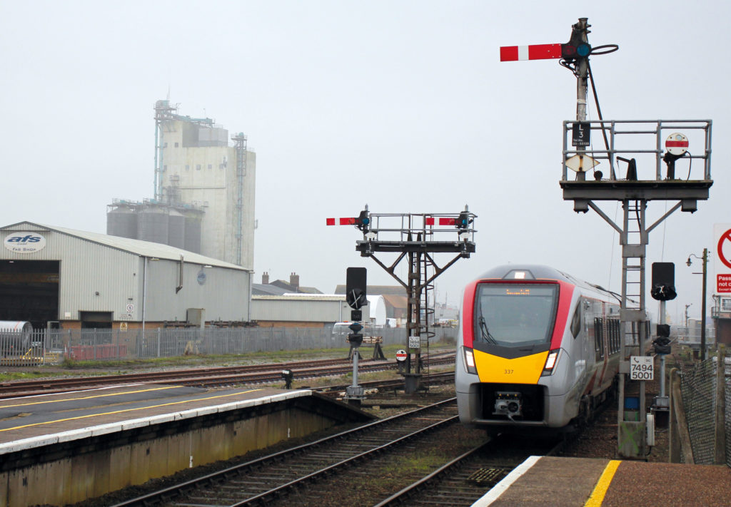
The block bells have fallen silent around Norwich and decommissioning of the McKenzie & Holland and Saxby & Farmer mechanical-lever interlocking frames and semaphore signals marks the end of an era dating back to the late 19th century.
Today, the new simple 2/3-aspect LED signals provide train drivers with a far superior forward view of the movement authority granted by the signaller sitting in the modern signalling centre at Colchester PSB.
Achieving this outcome was anything but straightforward, with significant volumes of work associated with the new signalling, swing bridges, track renewals and a multitude of level crossings, not to mention technical challenges necessitating innovative engineering solutions.
As the scheme entered the endgame, Mother nature intervened. The consecutive storms Ciara and Dennis made landfall during the two weekends of the 23-day commissioning blockade in February. Thankfully, the signalling project was able to continue with only minor re-planning, but concerns about safe deployment of a crane led to the cancellation of a separate bridge renewal project at Postwick within the same possession.
Wherry lines
The Norwich – Yarmouth – Lowestoft lines are marketed as the ‘Wherry Lines’ by the train operator, the name given in the late 18th century to a type of cargo-carrying sailing barge with large sails. For the purposes of this project, however, Network Rail preferred the acronym ‘NYL’ although this isn’t strictly accurate.
The Norwich station throat has a free-wired route relay interlocking operated from the 1986 NX panel at Colchester PSB, whilst Whitlingham Junction was resignalled under the Cromer project of 2000 utilising Vaughan-Harmon VHLC interlockings controlled by a modular control system (MCS) signaller interface located at Trowse swing bridge signal box. The latter products subsequently became part of the GE Transportation Systems (GETS) empire, the signalling interests of which have recently been acquired by Alstom, a supplier to the NYL scheme.
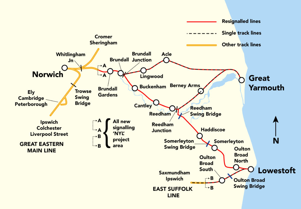
NYL signalling commences four miles out of Norwich near Brundall Gardens and controls forty route miles of railway (see diagram) including a single line serving Berney Arms, a station with no road access serving walkers, bird watchers and boaters.
Atkins selects ElectroLogIXS
Atkins (part of SNC-Lavalin) was appointed signalling and civil engineering contractor and designs integrator, managing a host of supporting contractors and suppliers (see inset). Network Rail was responsible for the integration of the intended Postwick bridge works and management of the permanent way and telecommunications teams. The delivery office was based at Lowestoft, while the principal office was at Stratford.
Atkins offered ElectroLogIXS computer-based interlocking technology, supplied by Alstom, which is already used extensively around the world (issue 176, July 2019). It communicates using internet protocol (IP), and off-site assessment has demonstrated compatibility with ETCS. The NYL project is the largest UK installation to date.
ElectroLogIXS has a small footprint and allows longer copper tail cables to be used, such as signals at 1,600 metres and wheel sensor cable as long as five kilometres. This facilitates the provision of fewer apparatus cases (LOCs), which can then be positioned close to a suitable track access point. Whilst maintainers prefer the safe, warm and dry environment of an REB to undertake maintenance and faulting duties, modern electronic interlockings are very reliable and require little maintenance. Any faults that occur will generate a report at the control centre, specifying which component needs to be changed, minimising the traditional time-consuming lineside fault diagnosis.
Signalling islands
The NYL lines are split up into six signalling islands at Brundall, Acle, Yarmouth, Reedham, Somerleyton and Lowestoft. Each island has a minimal power supply point (mPSP), providing the 650V AC signalling power supply to LOCs within the island. Each individual LOC will have a 650/110V mains transformer, ElectroLogIXS chassis, central processor input/output cards, Frauscher axle counter system, network switch, and UPS unit.
There is a suite of six different templated LOC cases, each catering for a combination of external signalling functions, built and wired in the Unipart factory. Once delivered to site, the LOCs are connected to power, twin-fibre cables installed to connect to the multi-services network (MSN). The lineside copper tail cables are connected using US military-grade plug couplers. Non-exposed Wago links provide technician access for circuit disconnection and testing.
Each of the six islands is allocated a separate ElectroLogIXS interlocking, which is situated at Colchester. The ElectroLogIXS input/output cards in the LOCs link the signals and points with the central interlocking processor at the control centre via the MSN, which is transmitted from the local FTN node to Colchester via FTNx.
The extent of concrete troughing is substantially reduced by using Nexans ruggedized axle counter cable with steel tape, wrapped with uPVC. In between the islands there is no power supply, nor any cabling apart from the FTNx communications and data carrier network. This was already in situ prior to the project and is a small green sheathed double-insulated super armoured cable (DISAC), a 24-fibre cable, designed to be laid on the surface.
Getting grid power to the islands
Electricity in this area is delivered by the distribution network operator (DNO) – UK Power Networks. Although there is sufficient capacity to meet the signalling power requirements, the challenge was to get cabling from their existing network to the location of the mPSPs at the railway islands.
A lot of work involved consultation with landowners and stakeholders in order to run cabling across third party land involving numerous methods of construction including Directional Boring, a minimal-impact trenchless method of installing underground utilities such as pipes, conduit, or cables in a relatively shallow arc or radius along a prescribed underground path using a surface-launched drilling rig. This technique, which offers significant environmental advantages over traditional cut and cover installations, is used when conventional trenching or excavating is not practical or when minimal surface disturbance is required.
The mPSP itself takes in power from the grid and outputs the signalling 650V AC, comprising transformers, switchgear, Uninterruptable Power Supply, a small standby generator plus space for a portable generator to be delivered by road and plugged in to cover for a prolonged mains interruption.
Signal boxes and swing bridges
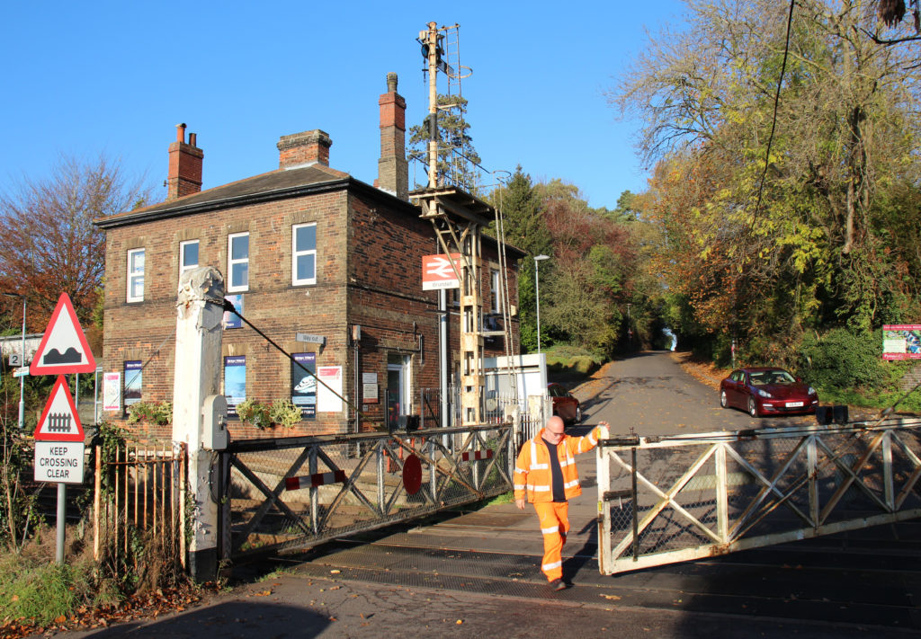
The original signal boxes at Brundall, Acle (the oldest box and frame installed 1883), Yarmouth Vauxhall, Cantley, Reedham Junction, Oulton Broad North and Lowestoft have been abolished.
The boxes at Reedham and Somerleyton swing bridges have been retained to operate the swing bridges across the Rivers Yare and Waveney respectively. These boxes are no longer block posts, with the associated shelf type relays and circuitry recovered. The two levers formerly controlling the protecting signals on the Up and Down lines respectively have been converted to ‘slot’ levers, used to release the new colour-light protecting signals controlled from Colchester. The lever locks and circuit controllers interface with the ElectroLogIXS via relays.
The signallers at Reedham and Somerleyton have full visibility of train movements in the area by means of the CCF (train running) display and may swing the bridges without reference to the signaller at Colchester as they are fully interlocked with the signalling system. They must ensure the bridges are back, detected in the home position with bridge bolts in position and slots pulled off in good time for the next train.
The bridge operating mechanisms have not been upgraded. At Oulton Broad Swing Bridge, a ground frame exists and the bridge operator must request a ‘release’ from Colchester to enable the bridge to be swung.
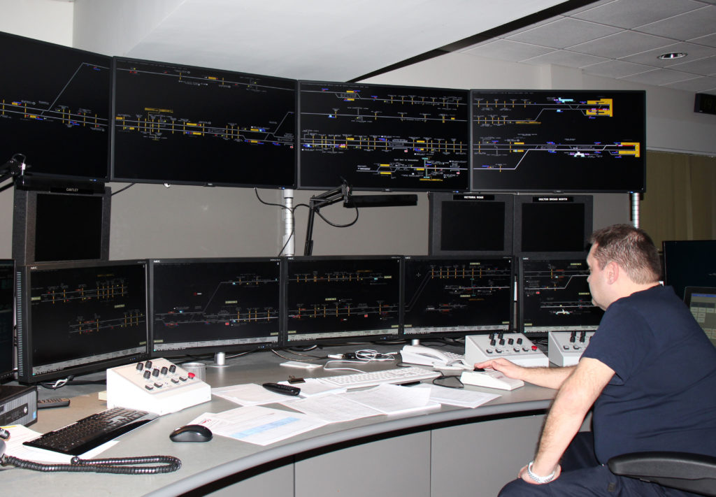
Control centre
The new signalling is controlled by the new Brundall and Lowestoft MCS VDU-based Signaller’s Control System (VSCS) workstations, which fringe with Trowse Bridge and Saxmundham boxes.
Anglia Route already has several MCS workstations in service, including several on the operating floor of Colchester PSB, so adding two more of the same brand greatly simplified staff training and flexibility for both signallers and technicians. There is a MCS training suite for signallers which may be programmed with a simulation covering the track layout of any of the MCS installations on Anglia.
Within the signalling centre, the MSN links the MCS, VSCS, ElectroLogIXS, MCB-CCTV control unit, Frauscher axle counter system and a firewall, thence communicating with the signalling islands via a Node interface to the FTNx network.
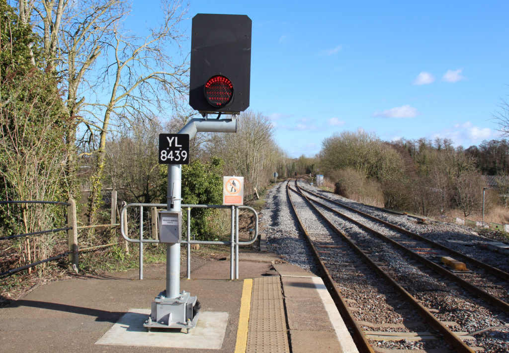
Train detection, points and signals
Frauscher RSR123 wheel sensors are used throughout for train detection purposes (axle counters), as barrier strike-in points and SPAD Prediction triggers. Point operating mechanisms are either in-bearer clamp locks or MkII rail point clamp locks. Signals comprise LED heads, two-thirds provided with ‘drop-down’ posts.
Signal Post Telephones (SPT) are provided at 22 out of 64 signals, provision of which was determined in conjunction with Network Rail and the train operator using the fixed lineside assessment tool (FLAT). It basically assesses the risk associated with each signal and the operational likelihood of a train being held at it and having to phone the signaller. With the extensive coverage of GSM-R, FLAT challenges the need to provide SPTs.
A white diamond symbol fitted to the signal post is used to indicate to the driver a signal not fitted with a SPT.
Train driver briefing packs for the new signalling were supplied by Gioconda, and the standard Network Rail ‘yellow notice’ produced in an easy to use booklet with track diagrams and lists of routes.
General acronyms
- CCF – Control Centre of the Future (displays basic live information from the signalling system such as signal aspects, routes set and train descriptions)
- ETCS – European Train Control System
- FTNx – Network Rail’s fixed telecommunications network IP cable
- GSM-R – driver to signaller radio system
- NX – ‘Entrance-Exit’ method of setting a route on a panel or workstation
- PSB – Power Signal Box
- REB – relocatable equipment building (also referred to as a “walk-in LOC”)
- S&C – Permanent Way switches and crossings
- SPAD – Signal Passed at Danger
- SPT – Signal Post Telephone
- TPWS – Train Protection Warning System (stops a train that has, or is about to exceed movement authority or speed limit)
- UPS – Uninterruptible Power Supply (battery backup)
- VHLC – Vital Harmon Logic controller (computer-based interlocking)
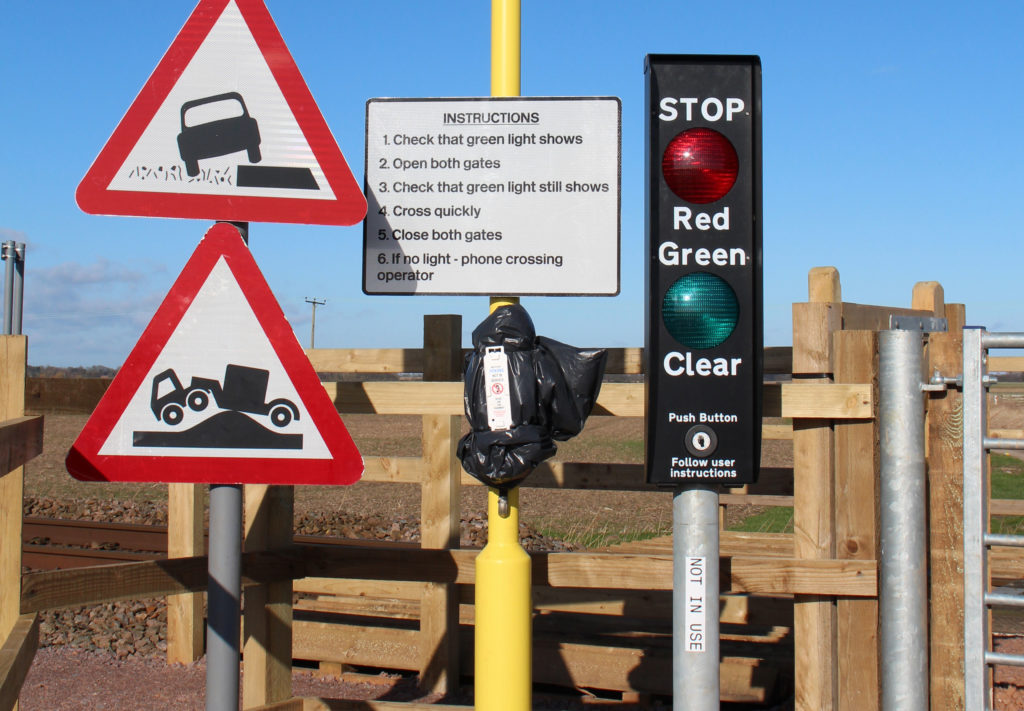
Level crossings
At the start of the scheme there were over seventy level crossings, including user-worked crossings (UWCs), and Sotera was contracted to carry out risk assessments to determine the level of protection needed and which crossings needed upgrading. Extensive local consultation was arranged to ensure road/footpath closures and diversions were clearly communicated to users.
The five manually controlled gates (MCG) have been replaced with manually controlled barriers with CCTV (MCB-CCTV). The existing life-expired MCB at Oulton Broad has been replaced with a completely new MCB-CCTV, whilst the existing MCB-CCTV at Victoria road has been re-controlled from Colchester. The ABCL (automatic barrier crossing – locally monitored) at Gravel Pit has been retained. The MCBs are driven directly from the ElectrologIXS cards. Auto-lower is not provided.
Annunciator actuation points (AAPs), consisting of Frauscher sensors, trigger a warning on the signaller’s CCTV control unit, causing the camera to display the crossing. The signaller then has to press and hold the LOWER button to operate the barrier sequence, prior to pressing CROSSING CLEAR to allow signal/s to clear. Where a station platform intervenes between the AAP and the crossing, ‘stopping’ and ‘non stopping’ AAPs are provided, the train description of the approaching train automatically informing the system which sequence is required. Auto-raise is provided.
The project installed the following new equipment:
- 6 ElectroLogIXS interlockings
- 168 Frauscher wheel sensors
- 5 green banner repeaters
- 12 In-bearer clamp lock points
- 62 LED signals with AWS
- 6 MCB-CCTV
- 2 MCS
- 11 MSL
- 3.5km new track
- 8 Rail Point Clamp Locks MkII
- 13 route indicators
- 2 TPWS over-speed loops
- 8 TPWS permanent speed-restriction loops
- 12 TPWS – Train-stop loops
SPAD prediction
For the first time on Network Rail, the intrinsic speed-sensing ability of the Frauscher wheel sensor is deployed to provide SPAD prediction. This functionality is used at Brundall (Up) and Cantley (Down) platforms, where the crossing protecting signals are located closer than the 50 metres required by the standard and stopping trains may encounter the signal at red.
Two wheel-sensors, positioned at specified distances from the level crossing, both detect how fast the wheel is travelling. The speed message is pulled out of the telegram to the evaluator and checked against a set speed which, if exceeded, will send a direct message to the crossing controller to immediately initiate the level crossing sequence and sound an alarm in the signal box. Atkins developed the system with Frauscher.
Methanol fuel cells
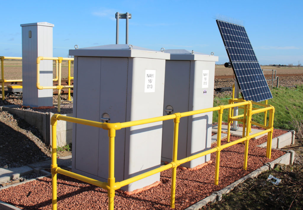
The risk assessments deemed that eleven UWCs be converted to miniature stop lights (MSLs). There are two different types. Four have stop signals within the strike-in and are therefore controlled by the ElectroLogIXS. One is fed from the signalling 650V supply, the other six are situated outside of a signalling island, devoid of mains power.
The solution adopted is the deployment of the VAMOS (Value for Money System) ‘plug and play’ controller built from industrial standard components, developed by Schweizer Electronic of Switzerland and approved to SIL 3 (safety integrity level 3). Frauscher wheel sensors trigger the sequence and there is no signaller involvement. Power is delivered by a local, renewable combination of batteries, solar panels and methanol fuel cells, specially developed for the project by Network Rail, Atkins, Unipart, Fuel-Cell Systems, and Energy Development Co-operative (EDC) Solar Wind. The project team took this through an extensive approval process and are keen for the technology to be exploited elsewhere on the railway.
GSM-R telephones for UWCs
Many UWCs are in remote locations without power and so, in another innovative development, solar-powered radio phones using mobile technology have been provided by DAC. Calls are routed through the GSM-R network to the GSM-R UK hub at Didcot, then pass onto the FTNx network to the concentrator at Romford ROC, continuing over FTNx to Colchester PSB, coming in on the signaller’s general telephone touch-screen, not the GSM-R terminal.
Several near-misses and a serious collision at Thetford have focussed attention on improving safety at UWCs. One key difficulty for signallers is knowing where a train is in a long block section and judging whether a level-crossing user calling in has sufficient time to cross safely. On the NYL scheme, train detection sections are arranged to ensure that the signaller can observe on the screen when trains are within five minutes of reaching the crossing.
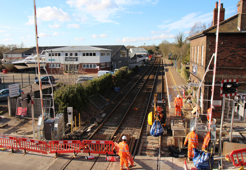
Staging the work
Although primarily a signalling renewal project, the opportunity was taken to carry out a much-needed simplification of the steam-age track layout and undertake some general relaying. As much work as physically possible was undertaken without requiring possessions, but most of the work was concentrated into five phases with line closures, during which the key tasks were:
- Phase 1 – October 2017 – S&C remodelling at Yarmouth and Somerleyton. A temporary relay interface was added at Yarmouth to enable levers to work the new points and signals.
- Phase 2 – February 2018 – Lowestoft S&C initial remodelling.
- Phase 3 – October 2018 – Reedham S&C remodelling and plain line renewals, new S&C secured out of use. Reedham Jn box closed and block section extended Brundall to Reedham Swing Bridge. Temporary suspension of train service via Berney Arms.
- Phase 4 – March 2019 – S&C remodelling and relaying at Brundall Jn with temporary relay interface to the points.
- Phase 5 – February 2020 – Level crossing works, S&C remodelling at Acle and Lowestoft, full signalling commissioning, track relaying at Hassingham. Twenty-three days of various line closures.
The Wherry lines have long been perceived as a Cinderella route with cascaded rolling stock and antiquated signalling. The successful introduction of state-of-the-art signalling and new Class 755 bi-mode diesel/electric trains brings the route decisively into the 21st century.
With thanks to David Taylor, Ian Martin and Stephen Deaville of Network Rail, and Douglas Shields of Atkins, for their help in the preparation of this article.
Other associated suppliers:
- Abacus Lighting – level crossing CCTV, and station platform lighting
- AECOM – track design
- CHG Electrical – remote condition monitoring
- Colas Rail – track units (S&C Alliance with Network Rail)
- Collis Engineering – signal posts
- Kier – minor civil engineering work associated with cable work
- Network Rail Telecommunications – FTNx data network and comms systems
- Newgate – level crossing barrier machines
- Northgate Public Services – IP phones for signals and networking systems
- Rail Signalling & Power (RSP) – point heating
- Ricardo Rail – independent safety assessments
- RJC Projects (Engineering) – heavy lifting contractors installing mPSPs
- Samuel James Engineering (Unipart) – mPSPs
- Thales – TPWS equipment
- Unipart Dorman – LED signal heads
- Unipart Rail – control cubicles, location cases, barrier lights, AWS