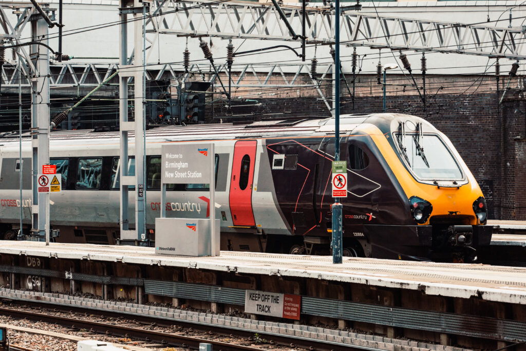
Rail Engineer has reported on the extensive West Midlands resignalling a number of times over the years, issue 160 (February 2019) covered the completion of phase 6 between Birmingham New Street (BNS) and Birmingham International stations. So, we were delighted to meet up with main contractor Siemens to learn how things had gone with the final phase 7 and the resignalling of the complex and tight BNS area, which resulted in the final closure of Birmingham New Street Power Signal Box (PSB) on Christmas Eve 2022 with control transferred to the West Midlands Signalling Centre (WMSC) at Saltley. The final phase presented a number of challenges for all involved.
Birmingham New Street station is the UK’s busiest interchange station outside London, handling over 140,000 passengers and around 1,200 trains daily – that is a train movement around every minute. The interlocking, installed in the PSB in the 1960s, was one of the last remaining Westpac Mk1 geographical relay interlockings in the country. Problems such as silver migration were a safety concern, and other assets such as lineside cables and interface relays were becoming fragile. The system wasn’t flexible enough to make the most of the limited infrastructure at the station and, with the increased footfall of passengers expected to increase over the coming years, signalling upgrades were needed.
The platforms at BNS are mainly covered with a large shopping centre above the station. The station’s structure, and its deeply urban nature, significantly reduce accessibility and space to located equipment. The layout of the station is also restrictive, with one bay, 12 through platforms, and four lines at each end of the station. The complex and tight layout results in signals often protecting fouling points that are very close to the signals. Passing a signal at danger, even by a small amount, is likely to infringe a fouling point and cause disruption. It’s also necessary for two trains to frequently occupy one platform, and to split a train or join two trains together.
To squeeze the track and platforms into the limited space, signalling design compromises have always been required. For example, Automatic Warning System (AWS) has never have been provided at BNS. Resignalling to modern standards has increased the challenges to identify and obtain the necessary derogations, and to achieve the operational requirements.
Planning and delivery
Work on BNS phase 7 started in 2017 with a two-year single option development stage, followed by a three-year detailed design, construction, and testing stage. The early planning and definition of the staging approach was crucial to minimise disruption to passengers and freight customers, and required close cooperation between all stakeholders including the many Train Operating Companies (TOCs) and Freight Operating Companies (FOCs) involved.
Under the original programme a six-day commissioning blockade of BNS would have been required, along with four 29-hour blockades. A complete shut down for such a lengthy period would have caused unsustainable disruption. So, the concept of staged interventions was devised. This used Rules of Route access and a full blockade on 25-26 December 2022, together with early closure on 24 December and a later start to services on 27 December. Services through and around the station ceased for 72 hours while 352 staff implemented the final elements of the scheme.
This approach involved 83 compressed stages carried out over two years, with rehearsals of the major stages in order to reduce risk of disruption in the final commissioning stage. Non-disruptive access was used throughout, which further complicated the planning work required.
This stage working approach required 12 platform closures, with the affected platforms segregated from the adjacent platform to minimise disruption and to maximise workforce safety. Through constant reviews the team managed a wide range of planned and unexpected events. During 2022, more than five million people visited the city during the Commonwealth Games, doubling the city centre’s footfall. The 70th anniversary of Queen Elizabeth’s accession to the throne and the resulting jubilee celebrations saw another surge of rail demand, as did travel around the time of the Queen’s funeral later that year.
The greatest challenge to the project however was Covid-19, which radically changed the way work could be delivered. Strict health and safety protocols had to be adopted to protect the workforce and minimise the risk of infection. Train ridership plummeted, but the importance of services to and through the station for key workers and critical freight services remained, and work had to continue with minimised disruption.
Over the four years of detailed design, the project integrated over 300 improvements of varying sizes that hadn’t been detailed within the original scope. This included on-track additional walkways to allow drivers to leave cabs safely.
Signalling technology
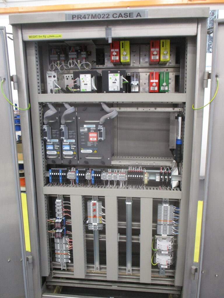
The Westpac Mk1 signalling was replaced by a processor-based Trackguard Westlock interlocking located in the WMSC along with the new control system. The Westlock manages Westrace Trackside System (WTS) equipment throughout the area, located in trackside location cases or relocatable equipment buildings, and connected over the Fixed Telecommunication Network (FTN).
Manufactured in the UK, this was the first deployment of this digital railway technology in the West Midlands, and introduced benefits such as faster route setting, the ability to operate with longer tail cables and improved immunity to traction interference, with the extensive use of fibre-optic instead of copper cables. Being processor based, the system is more flexible should modifications or changes be required and is capable of being used with ETCS.
Several novel signal indicators and axle counter developments were required to reduce clearances, compared to normal signalling. Thales axle counters were used for train detection and the signals replaced with LED units. The sheer scale of the project is such that 114 signals, 228 axle counter sections, 30 location cases, and eight relocatable equipment buildings were installed along with 11,000 metres of cable troughing protects, 78,000 metres of power and fibre cabling, and 245,000 metres of tail cables. For the power system, 35 Functional Supply Points (FSPs), four Principal Supply Points (PSPs), two Distribution Network Operator Cubicles (DNOs), and two 25kV ‘take offs’ from the Overhead Line Equipment (OLE) were also installed.
Plug coupling was widely used for the points (requiring retrofitting of plug coupled connections for many assets) and new signals in order to allow rapid changeover during rehearsals and the main commissioning.
Special bespoke brackets were designed to hold the mid-platform signals. The brackets wrap neatly around the bulkhead cladding fixing on the structural concrete beams to provide sufficient headroom on the platforms. This required careful design to work around station lighting systems to ensure compliant illumination.
Cable management provided another challenge, with hundreds of cables from the equipment rooms fanning out to equipment located around the station. This required excavations on each platform, often by hand, to allow cross-platform cable routes to be installed. Most of this work was carried out during short overnight possessions with the platforms reinstated, cleaned, and reopened for passenger use each morning.
Innovations
A number of new approaches were taken, some for efficiency, and some to meet the specific needs of the project. Twenty-six Train Despatch Equipment Units (TDEUs) were installed to show train despatchers information about the current status of the signalling in order to improve the number of on time departures. These innovative units were developed to provide improved efficiency, reducing risk of human error, and safer train dispatch.
Two 900 square foot, climate controlled, equipment rooms were built on site at the ‘A’ end of the station to optimise the use of restricted space, to comply with the sub surface fire regulations, and to allow construction while the station remained open for passengers. Each room houses the equivalent signalling control equipment of four traditional REBs along with separate rooms for telecoms and Electrical & Plant (E&P) equipment.
Combined with the longer tail cables that can be used with WTS, this allows a centralisation of the trackside control equipment, reducing the quantity of trackside location cases and reducing the risk of staff accessing and working in trackside locations in the confined environment.
At the ‘B’ end of the station, space was freed up by moving redundant equipment. This allowed the use of more traditional signalling REBs, although some ‘double stacking’ was necessary to fit everything into the space available.
In order to help drivers and signallers fully understand the new signalling, extensive use was made of simulator-based training. Twenty-six signallers used an interactive 3D representation of the routes into the station to familiarise themselves with the changes. A 3D model of a train cab was created to allow drivers to virtually learn the route. This not only provided a safe system to train but also allowed useful feedback to further improve operational effectiveness.
Relocatable temporary signals at platform ends were used in order to facilitate the platform closures required. These allowed the new signals to be installed during each stage and enabled rapid changes to the signalling layout. The bases and posts were designed to be modular and adjustable, allowing them to be relocated around the station for the following stages.
Traditionally, in Great Britain, signalling tail cables are limited to 200 metres in areas of OLE to reduce the risk of induced voltages causing failures or false operation. This traditionally meant that a suite of signalling location cases is required near to most signals. Longer tail cables allow fewer lineside location cases/REBs for a more efficient design, particularly where space is constrained. The cost savings to provide safe accessible location suites were significant.
The pioneering use of long tail cables in Network Rail, required extensive modelling, site testing of induced voltages, detailed analysis, and on-site equipment trials to demonstrate safe and reliable operation. This saved the need for five location suites and the methodology developed is now being replicated on projects across the country.
Thales axle counters were used, these being the local standard for train detection. However, a number of developments were introduced for the complex and compressed BNS track layout, with some clearances reduced by half following analysis and site testing. Reliability was enhanced through the use of two-out-of-three, rather than the traditional two-out-of-two processor architecture.
Communication between the axle counter processors was via fibre optic links. A direct communication link was also used between the axle counters and the Trackguard Westlock interlocking, the first time this had been done in Network Rail, and this removed the need for a relay interface. Duplicate axle counter heads with diverse cable routes were also used to allow automatic changeover between heads should one fail or suffer a cable strike.
Given the restrictive nature of the site, localised modelling was used to position key signals and indicators to exceptionally fine margins to achieve the requirements of the signal sighting process and assess potential ‘read-across’ issues.
Control system technology
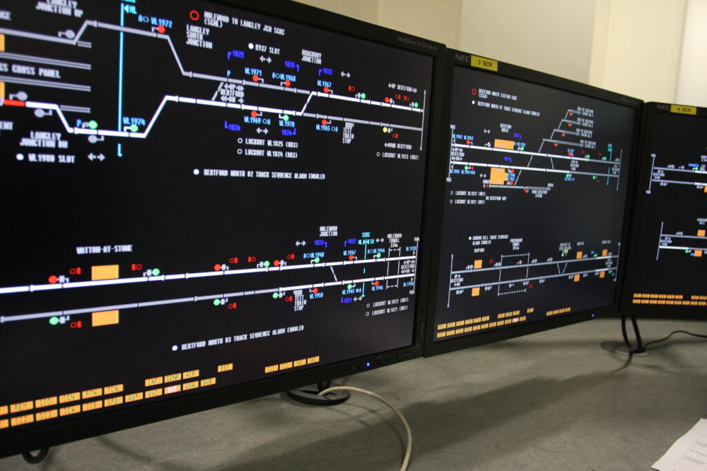
As part of phase 7, the BNS area was recontrolled using a processor-based Controlguide Westcad workstation located at the WMSC. Train operator staff are now co-located with Network Rail signalling staff so that they can work together to problem solve more cohesively and reactively. This reduces the impact of late running services or platform changes by use of the modern control system to increase route reliability and platform flexibility.
A number of modifications were made to vastly improve railway operations. Although the system delivered in the 1960s allowed for some bidirectional movement in the station area, this was not possible on the approaches. The phase 7 work created a bi-directional loop for Platforms 1 to 7 (via Monument Lane) and Platforms 7 to 12 (via Five Ways and the Gloucester line) in addition to connection to a number of new sidings. This improves flexibility and allows line speeds to be increased to reduce journey times.
Extensive telecoms work was also required. This involved designing and installing three new nodes on the FTNx IP telecoms network and 10 existing nodes were upgraded. A two-stage approach was taken to create the telecoms network to allow signalling rehearsal testing 12 months before the final commissioning, with a controlled changeover to the final configuration. At the WMSC the existing analogue telecoms concentrator was replaced with a digital system to improve call handling.
Sustainability
All partners in the project committed to sustainable delivery, as they were very aware of the large number of railway neighbours that were likely to be affected by the work. One example was the creation of a new, award-winning site welfare/depot facility, around 2km from BNS on an undeveloped site. Having been cleared and improved, the new depot was fully solar powered, saving around 75,000kg of CO2 emissions over three years.
Electric tools and equipment were used to reduce emissions and to improve safety by reducing the flammable liquids on site. Battery-operated power tools, mobile elevating work platforms, solar powered welfare units, and solar powered tower lighting all contributed to the sustainability objective.
Delivery of the PSPs and REBs at Monument Lane required a 1,000-tonne crane lift over the main lines to Wolverhampton from an adjacent park. A temporary access road and pad were constructed, which involved cordoning off a section of a primary school playing field. Siemens Mobility worked closely with the both the school and council, and supported the school with construction of a new sensory space and the city with a donation to the charity Trees for Life, to support the planting of more trees.
Occupational safety
Getting everyone home safe every day is a Network Rail commitment, so as part of the safety strategy, and with most of the work under cover and in the confined station area, a plan had to be implemented for preventing dust inhalation. Tools with dust extractors were used to protect the teams. Throughout the Covid-19 emergency, even greater protection measures had to be implemented, so air-fed face masks were used to overcome the hazards from the dusty environment, which then formed part of the project’s Covid-19 protection measures.
Conclusion
There was no chance of a lengthy closure due to the geographical location of BNS and the critical nature of the infrastructure to the economy. By adopting a collaborative approach, using detailed knowledge of the existing infrastructure and an innovative application of digital technologies, the team successfully delivered a major upgrade with minimal disruption, despite a wide range of challenges.
Passengers and freight operators are already seeing an improvement in their journeys through this central hub, with fewer unplanned stops outside the station and more on-time arrivals.
With thanks to Steve Bick, project director, and Andrew Cardiff, senior project manager at Siemens Mobility Limited for their help with this article.
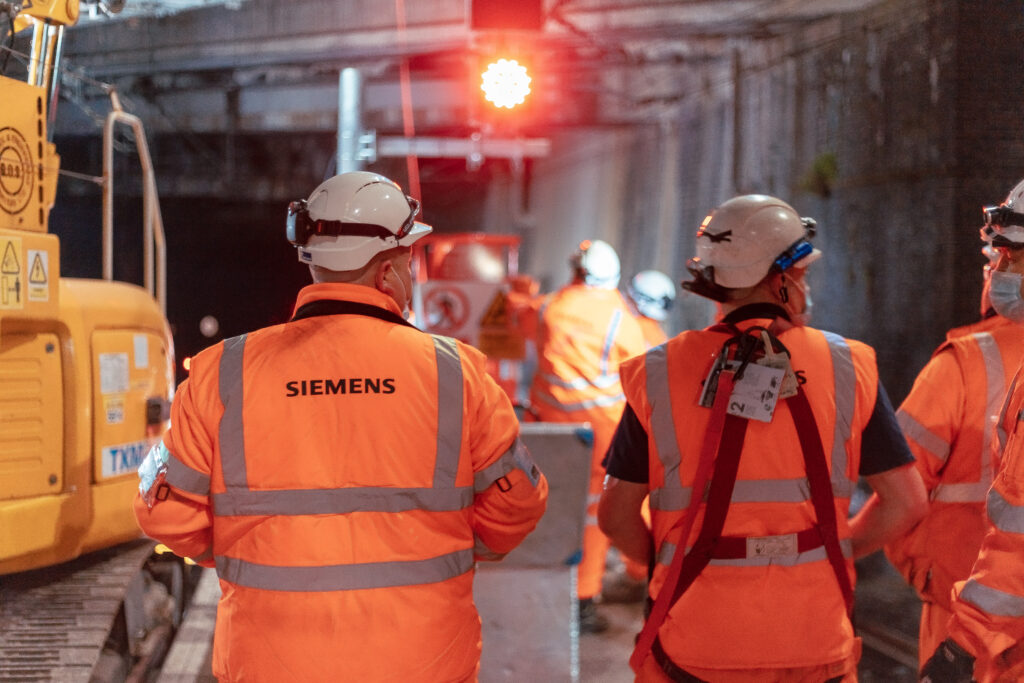
Lead image credit: Siemens