

The approach to overhead contact system design on electrification projects has evolved in recent years, with a focus on avoiding costly bridge reconstructions.
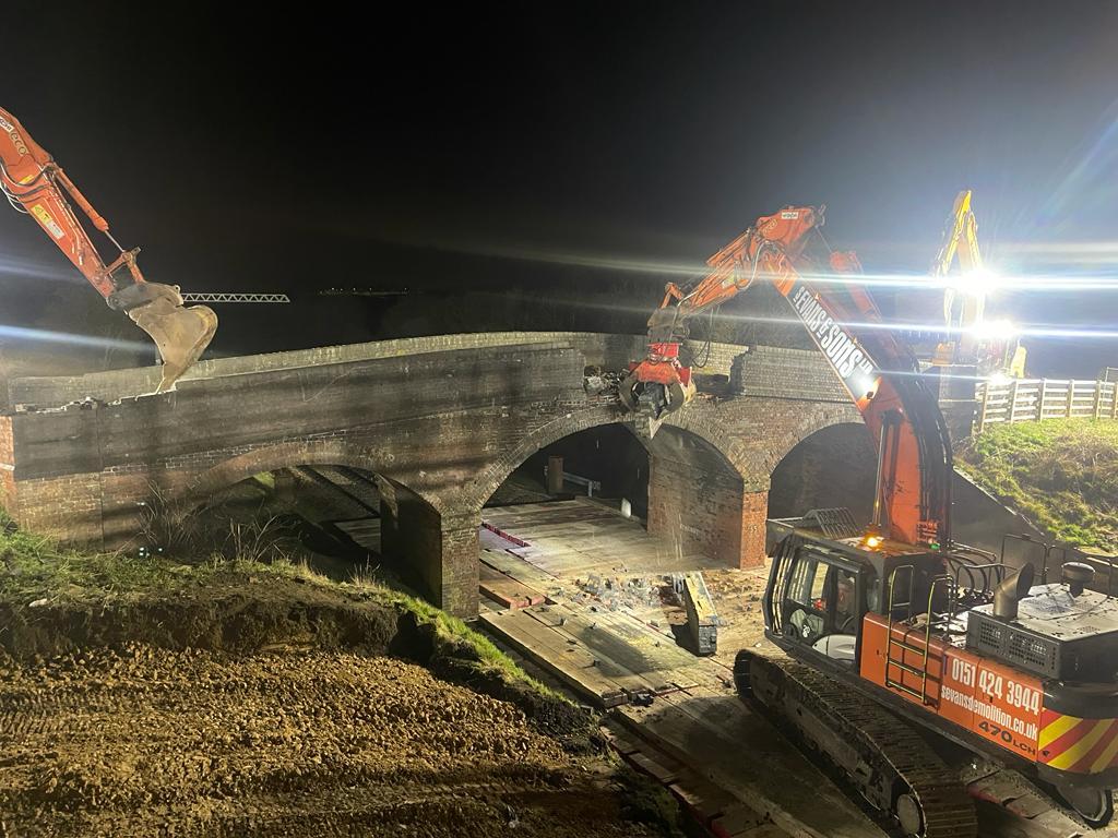
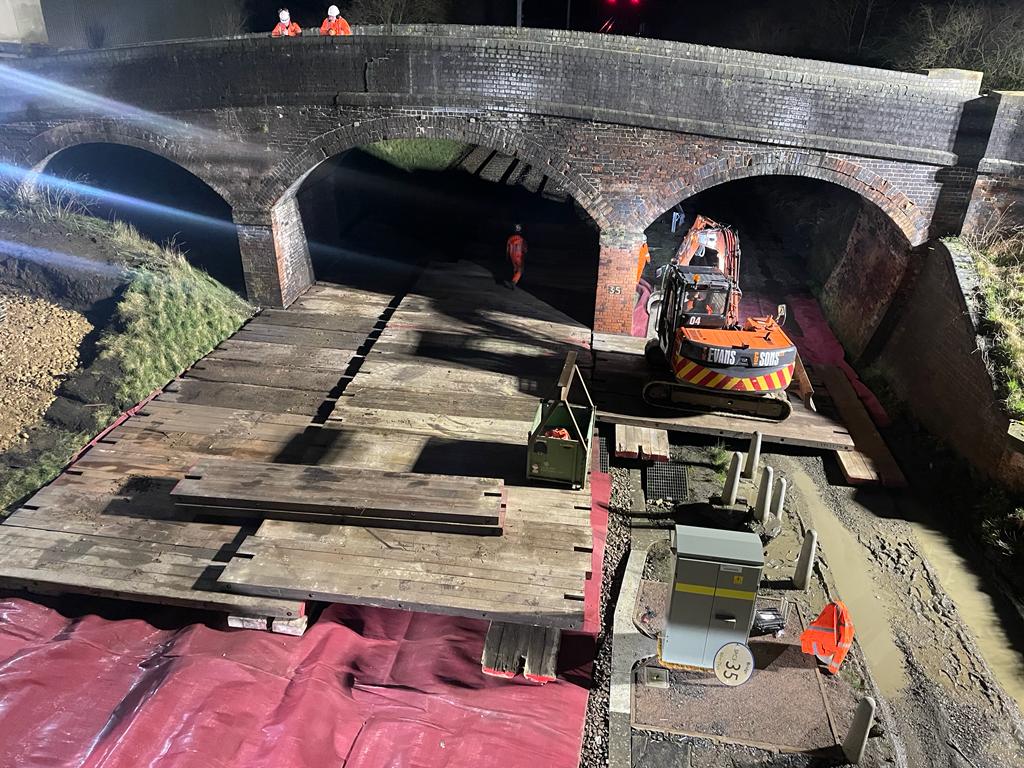
In the UK, most rail bridges were built long before overhead catenary systems were a design consideration. Hence, it is difficult to achieve the necessary clearances to the 25kV system used for mainline electrified routes in the UK. This has unfortunately resulted in a lot of bridges being demolished and rebuilt to modern standards as part of electrification projects.
Electrical and mechanical clearances to overbridges have always been a challenge in the UK. In 1974, stress graded bridge arms were introduced to limit the dynamic movement of the OLE (Overhead Line Equipment) system. This allowed a new category of ‘special reduced clearances’ to be introduced which required the consent of the safety authorities to reduce dynamic clearances down to 125mm, which is the worst-case air gap between the live wires and the underside of the bridge, as well as the clearance to the vehicle gauge below.
In more recent times Network Rail introduced a new approach where dynamic clearances as low as 20mm could be considered, depending on site constraints. The air gap can be reduced to this level by implementing Voltage Controlled Clearances (VCC) using numerous technologies such as Surge Arresters, typically located either side of an overbridge.
Twenty years ago, pantograph profiles were mainly drawn manually with CAD cells where variables such as track tolerances, uplift of the wires, sway of the vehicle, and OLE tolerances were factored in to create a worst case position of the pantograph at overbridges. However, these days there are a lot more variables to consider with recent standard changes. One example is encroachment or head roll which factors in the dynamic position of modern pantographs.
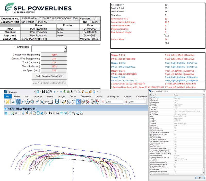
Dynamic pantograph gauging tool
Another change in the industry is a move towards probabilistic techniques which can reduce the clearance requirement by 50mm. This doesn’t sound significant on its own but with other tolerances being reduced it can sometimes make the difference to avoid costly interventions at bridges.
At SPL Powerlines we have recently developed a new dynamic gauging pantograph tool which will be a key aspect of how we approach design at low clearance bridges in the future. This will ensure that we can deliver efficient electrification across the UK, minimising our design and build costs.
We typically work with 3D federated models with geospatial coordinates which allows designers to be more precise than ever before, however this brings more complex variables for design engineers to consider.
There is a balance to be struck between creating design tools that are fully automated and allowing designers to consider the engineering issues at a bridge location and take ownership of the design process. Our approach is to develop design tools that are intuitive, easy to use, and allow our team to focus on the engineering aspects of the design.