Guest writer: Justin Moss – Strategic Development Manager at Siemens Mobility.
In March 2020, the Department for Transport (DfT) published its ‘Decarbonising Transport’ paper, outlining the role the transport sector has to play in achieving the government’s target of net zero greenhouse gas emissions by 2050.
The paper marks the start of a process which will see the government set out the policies and plans needed to address transport emissions and to realise the broad range of benefits that decarbonisation will deliver, improving people’s health, creating better places to live and travel in, and driving clean economic growth.
It also recognises that electrifying more of the railway will be necessary to achieve this, with major projects including the Great Western main line and Midland main line upgrade programmes already set to greatly expand the electrified railway network.
However, whilst electrification is set to have a major impact on the decarbonisation of the railway, the predominance of Victorian infrastructure across the network has historically presented projects with major engineering and cost challenges.
This is especially the case when 25kV catenary equipment has had to be installed underneath existing infrastructure, such as bridges or tunnels. Until now, this has only been possible by removing and replacing the existing structure, or lowering the track, which is not only costly and time consuming for the project but can also be problematic if the structure is listed or requires utility diversions.
The problem – electrical clearance
The issue that has arisen when negotiating these structures has been the need to provide sufficient electrical clearance. Clearances are defined by standards and legislation and are an essential factor when designing and developing overhead line systems. If adequate electrical clearance cannot be provided, then scheme designers have had to consider whether to modify or renew the bridge or tunnel, or alternatively to lower the trackwork running through it.
Clearly, expert knowledge of electrical clearances throughout the overhead line design process has been critical, enabling different scenarios to be modelled and assessed. To ensure the electrified infrastructure doesn’t suffer electrical flashovers, which could result in catastrophic failure of equipment and significant operational disruption to the railway, the designers will have taken into account a range of factors, including normal and extreme environmental conditions, pantograph uplift and maintenance tolerances.
These have been difficult decisions, not only because of the impact they would have on a programme’s costs and timescales, but also in their contribution to the overall embedded carbon for the delivery of the scheme. Addressing these issues has been a key deciding factor as to whether some electrification projects have been viable.
The challenge then has been to reduce electrification costs and shorten programme timescales by eliminating the need to undertake these disruptive, time-consuming and costly infrastructure works.
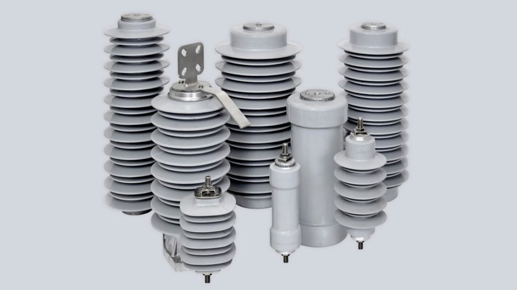
Surge arresters come in all shapes and sizes.
The solution – Surge Arresters
In response to this issue, Siemens Mobility’s electrification team has developed an engineered solution which uses a 25kV surge arrester in circuit with the overhead line system. This enables reduced electrical clearances to be applied and delivers significant cost and delivery benefits.
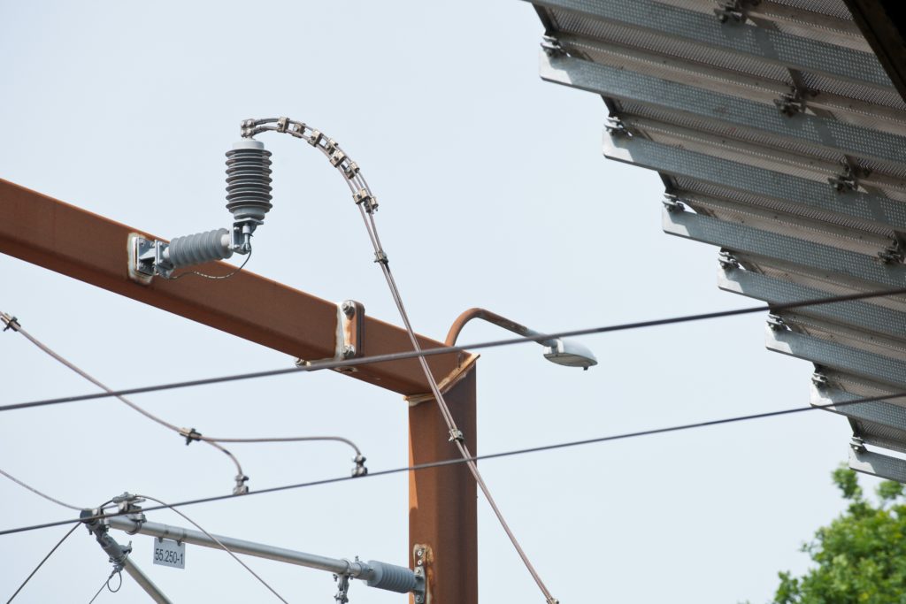
By introducing surge arresters into the electrification system at bridges and tunnels, if over-voltages do occur, for example through a lightning strike, the surge arrester reduces the impact by a magnitude of voltage which complies with the required electrical clearance values between an overhead line and structure.
Depending on the required protection level, surge arresters can be applied to the overhead line equipment at both sides of the structure and for each contact system running through it that requires a reduced electrical clearance.
As described in issue 158 (December 2017), on completion of extensive test trials in 2017, Siemens Mobility’s surge arrester has been approved for use by Network Rail and has now been designed and installed on the UK network since December 2019, with the first installation being in Cardiff, where restrictions caused by the proximity of a canal, combined with a rail intersection bridge, meant that the track could not be raised or lowered to accommodate compliant electrification equipment.
The system is also being considered at other locations in the UK, such as Wales and Borders and the Transpennine Route Upgrade.
To monitor the frequency and cause of over-voltage incidents, a counter module can be installed with the surge arrester that can be read remotely from a track side position using Bluetooth technology. In contrast to simple spot checks, these long-term measurements automatically provide optimum information for trend analysis and make a valuable contribution to asset management.
Already proven in projects, surge arresters are removing one of the major obstacles that has held back many electrification projects in the past. By reducing the overall cost of programmes and shortening delivery programmes, the application of this technology will reduce disruption for passengers, improve performance and deliver cleaner and quieter journeys, making a significant contribution to the industry’s decarbonisation targets.
Justin Moss is strategic development manager – rail electrification at Siemens Mobility.
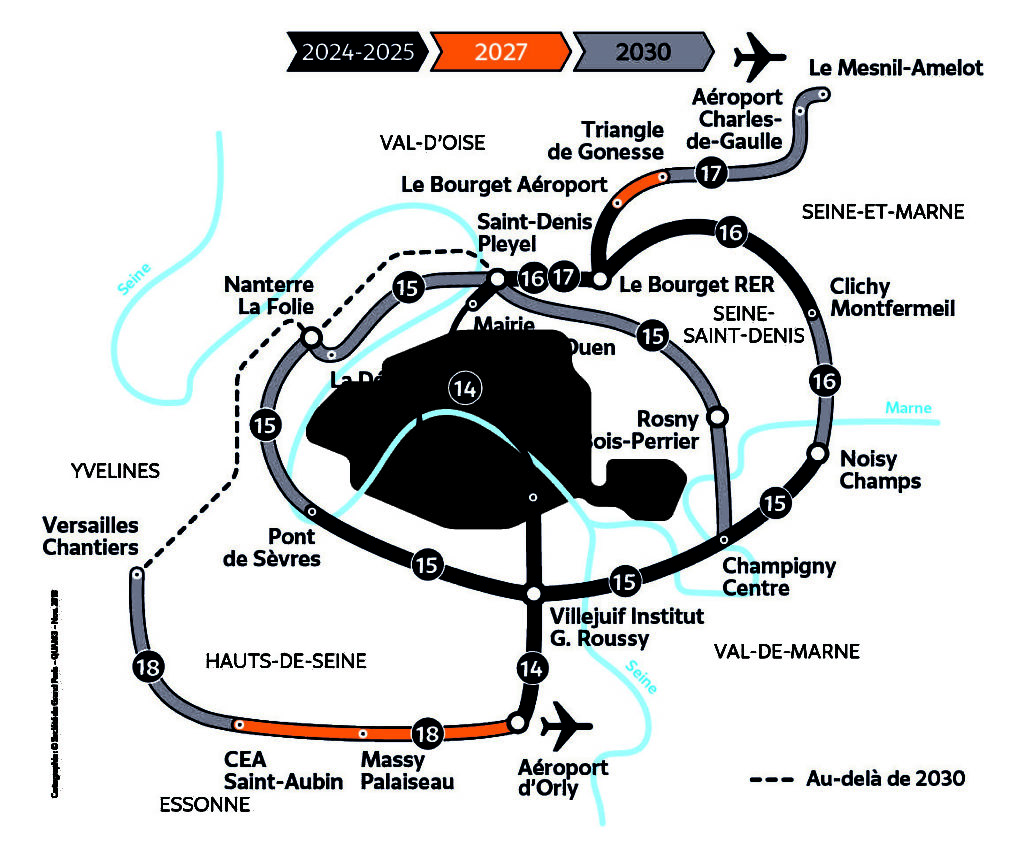
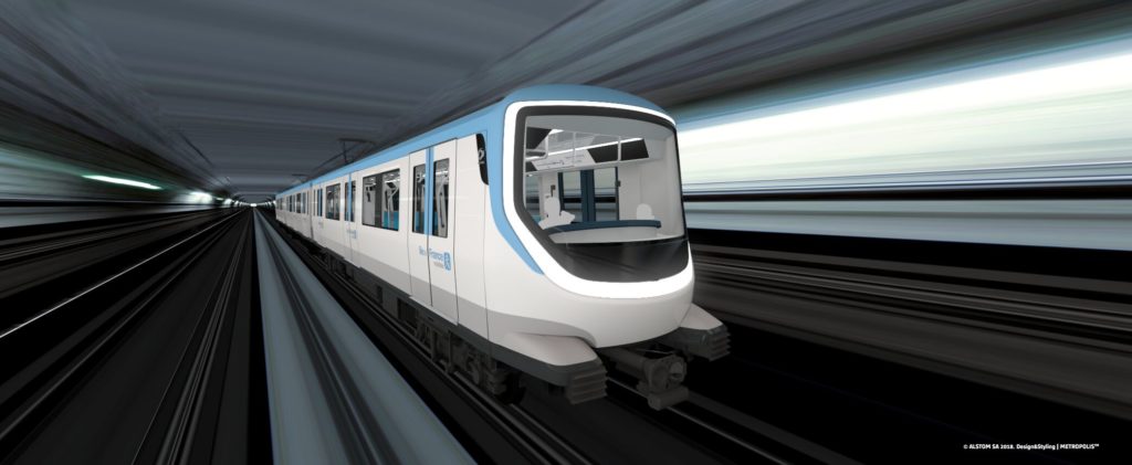
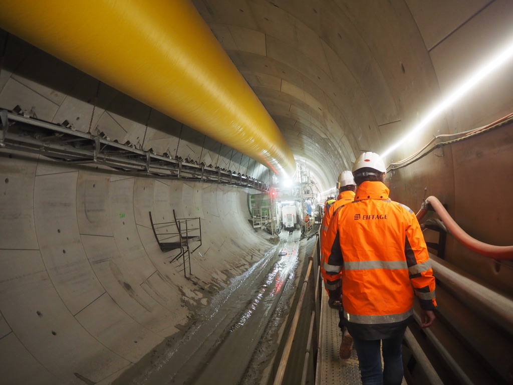
The Greater Paris project seeks to transform the French capital from a monocentric city to a multipolar metropolis. At the heart of this ambitious plan, combining urban and economic development, is the Grand Paris Express, a new-build automatic metro designed to link up and breathe new life into the Paris suburbs and beyond.
To dig deeper, Rail Engineer met with Alexandre Missoffe, managing director of Greater Paris Investment Agency, which has several tasks on its hands. In addition to tracking and encouraging investment, both within the Paris region (Ile-de-France) and in the construction project itself, it also liaises with other cities worldwide.
“From London to Singapore, Toronto, Hong Kong and Moscow, we are all exploring ways to make our cities sustainable with affordable housing, an efficient economic situation, clustering activities,” explained Alexandre Missoffe. “The fundamental nature of the issues we are facing is the same: how to expand our cities without pushing people too far outside the centre? How to resist urban sprawl without creating too much urban density?”
Given these interests in common, the cities are working to create a network for sharing their experiences, know-how, news and views. “We meet at events and organise them too,” he added. “For instance, our Agency organises tours of the Greater Paris region for foreign visitors, like the mayor of Toronto, for example, who came over in October 2019 to see our new solution for affordable housing. Then, in November 2019, we were in Hong Kong to meet with MTR (Mass Transit Railway, the local public transport network). This engagement with our foreign counterparts is extremely important.”
Think tank
Another mission for the Agency is acting as a kind of ‘think tank’ for governments and companies at local and national levels, both pushing for and carrying out proposals to boost the appeal of the Greater Paris region. As an example, the Agency is exploring the challenges of energy sustainability.
“By 2030, the total energy needed to power the Grand Paris Express, plus all the new housing and industrial activities under the Greater Paris umbrella, will represent the output of three nuclear power plants!” Alexandre Missoffe said.
“Of course, we won’t be building these plants – the energy won’t be produced within the Paris region, but sourced further afield,” he hastened to add.
However, for companies such as manufacturers in the auto industry, for instance, the cost of energy rather than salaries is more of a priority. This is down to latest generation 4.0 factories that require fewer workers but more and more computers, robotics, machines and equipment that consume a lot of energy.
“So, if you are a car manufacturer or a company in a high energy consuming industry, the cost of energy is a key criterion when deciding where to locate your business,” explained Mr Missoffe. “Today, they have to anticipate increases in energy demand and are looking for an affordable, carbon-free and safe energy supply system for the decades to come. Hence, the reason we are working on this strategic topic, amongst others, with the French Government.”
Innovation, time and risk-taking
“If we were to build the Grand Paris Express we are building today 100 years from now, it wouldn’t be cheaper or quicker, and probably not better,” reckons Mr Missoffe. “This is one of the great paradoxes of innovation in the construction industry.”
Building the Paris Metro was approved in 1898 and the first line opened in 1900, 15 months later. But, for this latest transport system, the law was adopted in 2010 and the first line, a section of Line 16, is scheduled to open in 2024. Why so long?
“There’s a tendency to be more risk averse for the core structural elements of all major construction projects, like Greater Paris, that involve large sums of public money, that are on tight deadlines and are very much in the media spotlight,” believes Mr Missoffe. “The people and companies involved in the project don’t want to be the ones responsible for a major delay or accident. Consequently, when given the choice between one technology or technique that seems to go faster, is cheaper and better, and another that has been proven over the past 15 years, they tend to opt for the latter.”
“Some new technologies were used when tunnelling Line 14 of the Paris metro under the city and there were issues,” says Mr Missoffe. “Most memorably in 2003, when the playground of a school in the 13th district of Paris [south of the city] collapsed!”
Fortunately, this incident occurred in the early hours of a Saturday morning, so nobody was hurt. However, all the engineering firms who worked on this line are now working on the Grand Paris Express. Bearing in mind the risk, they are naturally tending to stay on the safe side by using proven technologies.
“In my view, it’s absurd to build a network for 2030 using technologies that are decades old,” commented Mr Missoffe. “Surely we should be exploring next generation innovations for 2050.”
On the upside, however, he pointed out how this risk aversion doesn’t rule out innovating in other, less ‘risky’ areas, such as regenerative braking for the metro trains and geothermics, re-using tunnelling waste, testing new types of fibre-reinforced concrete, or boring with a Vertical Shaft Sinking Machine to save time and space.
Mountains of paperwork
The construction schedule is also being impacted by today’s stringent safety regulations and labour laws, “mountains of paperwork”, environmental obligations for protecting fauna and flora, and efforts to disrupt inhabitants as little as possible. A far cry from the ‘good old days’ when constructing Line 1 of the Paris network.
“Back in the day, they literally cut Paris in half for 15 months to build using the cut and cover method,” pointed out Mr Missoffe. “Today, creating such massive disruption to Parisians is totally out of the question!”
But, as he rightly points out, all these constraints are not unique to the Greater Paris project, but a tendency for all major construction projects.
Laying down the law
To a certain extent, special legislation has helped overcome some loopholes that might otherwise have slowed up progress even further. In 2010, the French Parliament passed a law, the Greater Paris Act, granting special powers, including for expropriation.
According to French law, the subsoil under a property right down to the centre of the earth belongs to the property owner. When tunnelling under it, constructors generally pay compensation of around three euros per square metre. However, when apartment buildings are involved, with multiple owners, the process becomes more complicated.
“You divide the compensation between the flat owners, but if any of them disagree, you have to settle in court,” explains Mr Missoffe. “Now, bear in mind we’re talking about tunnelling under 20,000 properties for the Grand Paris Express, the majority of which are apartment buildings. Imagine the time, the number of lawyers and judges, and money it would have taken to settle all the compensation disputes. It would take years!”
Fortunately, the new decree waives the obligation to make payments to property owners when tunnelling at a certain depth. Above this level, even if the volume of subsoil in question is technically worth just one euro, it pays out a minimum flat rate of €2,000. Problem sorted?
“Well, yes, this part of the construction might well have posed a challenge, but fortunately we anticipated and resolved it,” said Mr Missoffe.
Money matters
The Greater Paris Act also created the Société du Grand Paris (SGP), a special purpose body that manages the project and directly receives revenue from three taxes to reimburse the debt.
“In other words, this income, which amounts to around €700 million annually, can’t be used for any other purpose,” he explained. “Back in 2014, construction works had not started but the Société du Grand Paris was already provided with around four billion euros, a large amount exclusively secured for the future metro. The money is now spent, creating a debt that will be gradually paid off.”
Jobs to build, and beyond…
Who’s awarded the contracts to build the Grand Paris Express? “People might think that, since it’s a state-funded project, French firms get preferential treatment. But this isn’t the case,” Mr Missoffe insisted. “There’s so much work that we need both French and foreign companies to meet the deadlines. Indeed, major parts of the project have been allocated to foreign companies and the French are happy about this because they need these partners. Plus, they get to benefit from their expertise, know-how, and skills.”
At the same time, he says, the skills for building transport infrastructure are really lacking and becoming increasingly rare. Furthermore, Greater Paris is competing with other global cities to attract the best workers.
“There are many other major projects planned or ongoing over the world, like Crossrail or Rail Baltica, so we are competing with our counterparts to attract the best talents,” he explained. “While engineers may well want to work for us, they might get offered a 20 per cent salary raise to join another project. So yes, it’s a question of money and quality of life, but, most importantly, we are seeing a shortage of engineering talent for tunnelling work on major infrastructure projects.”
In addition to the jobs created to build the Grand Paris Express, once up and running, it is expected to significantly open up employment opportunities in the region. Line 16, for example, will provide a link between Clichy-sous-Bois, a suburb to the east of Paris with the highest unemployment rate in France, and Charles de Gaulle airport to the north. “There are thousands of jobs linked to the airport hub and logistics activities, but they can’t find people to fill them,” complained Mr Missoffe. “This is largely because people can’t access the jobs, since there is no transport infrastructure.”
There are currently 2,140,000 inhabitants in inner Paris and two million jobs. “This is ridiculous! The right balance is one job for every two inhabitants,” he exclaimed. “But today, because of this imbalance, plus the fact that the current transport systems (Metro and RER commuter rail network) are radial and all feed into the centre of Paris, too many people are travelling in and out of the city to work.”
This explains why much is riding on the orbital Grand Paris Express, which should encourage more people to live and work around Paris, and so relieve stress both on themselves and the existing transport systems.
Staying the course
For the Greater Paris Investment Agency, keeping the initial vision in its sights is one of the big challenges ahead. “If we lose this vision, the project will become just the sum of many parts. There is a danger of skipping some parts of the whole so, at the end of the day, Greater Paris no longer makes the sense it should,” Mr Missoffe reckons. “Of course, we must adapt the vision approach over time, but always bearing in mind where we want to go with Paris for the next 200 years.”
Fortunately, support for Greater Paris has remained constant despite political shifts over the years. “The project was launched by President Nicolas Sarkozy in 2009, then President François Hollande followed in 2012. While the latter certainly didn’t agree with a lot of what his predecessor had said and done, he kept the project on track. As has President Macron today.”
The 131 local communities making up the Greater Paris region support political parties across the political spectrum. Yet, according to Mr Missoffe, they all vote unanimously for every proposal concerning the project – the Grand Paris Express and urban development plans. “Everyone is in favour, regardless of their agendas. They might disagree over the details of a proposal, of course, but nobody wants Greater Paris on hold.”
Mr Missoffe summed up: “Paris and its region, Ile-de-France, currently generates one third of the country’s GDP, which is already massive. If the Greater Paris project works out, it will create employment, boost the attractivity of the region, and encourage new activities to locate here.”
Data communications specialist Westermo has introduced two LTE (Long-Term Evolution) routers to its Ibex range of wireless solutions for reliable and secure data communications within rail applications.
The Ibex-RT-330 and Ibex-RT-630 are compact LTE routers, developed to meet the growing demand for continuous coverage onboard trains and to support applications such as data offloading between stations, monitoring and remote maintenance access.
The LTE routers ensure reliable, continuous, high-speed remote access data communications in extreme operational environments, connecting the moving train with the signalling control centre over a mobile network.
Two models
The Ibex-RT-330 is a mobile LTE router offering high bandwidth to support multiple applications, such as data offloading and remote monitoring.
The Ibex-RT-630 is a mobile LTE and WLAN router/gateway, which offers outstanding performance and rugged internet connectivity back-up to enable hybrid train-to-ground installations with a single device.
Both routers support hardware offloaded VPN, for high performance capabilities. They also support LTE CAT12, which provides ultra-high data throughput and aggregation of carrier frequencies to serve the most bandwidth-demanding applications worldwide.
Multiband GNSS (Global Navigation Satellite System) support enables the use of multiple frequencies for extremely high accuracy positioning and deployment worldwide.
The routers have EN 50155 approval for onboard applications and are designed to withstand the challenging environments and demands of rail applications, including constant vibration, extreme temperatures and humidity.
The devices are IP66-rated for prevention of water and dust ingress and have an operating range of -40°C to +70°C. High-level isolation between all interfaces protects against overvoltage and flashover. These features increase reliability and extend the mean time between failure.
A compact design enables quick and easy installation into tight spaces onboard trains, while configuration and unit replacement are simplified by a SIM-card memory for configuration parameters. Dual-SIM ability allows for further performance optimisation. A unique SIM-card tray makes SIM handling in the field effortless.
Ibex family
The Ibex product family, which includes wireless access points, clients and bridges, has been developed for rail applications such as train-to-ground systems, wireless inter-carriage links, WLAN solutions for public onboard Wi-Fi, remote access and vehicle positioning.
Together with Westermo’s extensive range of Ethernet devices, this forms the world’s most complete data communications portfolio for the rail industry.
In addition to rail applications, the products are ideally suited for deployment in applications with severe operating conditions and tough environments, such as traffic systems, mining, maritime and factory automation.
Guest writer: Tim Flower – professional head of maintenance at Network Rail.
Intelligent Infrastructure is Network Rail’s digital asset performance management programme, using technology to turn data into intelligent information so the frontline and supporting teams can work smarter and more safely to deliver improved services for passengers and freight customers.
Ultimately the goal is to reduce expenditure whilst improving infrastructure availability by:
Understanding the probability of individual asset failure;
Predicting when failure will occur;
Forecasting the impact on the operational railway;
Planning intervention prior to disruption to train services.
The programme isn’t just about introducing huge amounts of new technology, it has been carefully designed to look at how we can maximise the value from the data we have whilst working closely with our research and development programme to make sure we continue to be at the forefront of technology introduction.
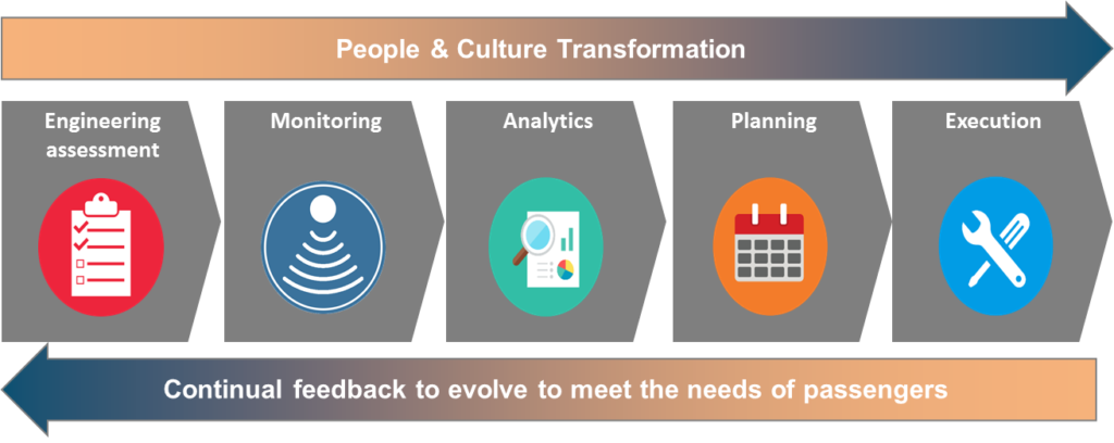
The building blocks of the programme.
People and culture transformation
Throughout all stages of the programme, we have recognised that there will be significant changes to how our teams interact with data and technology, and how work will be specified, planned and delivered. Successful delivery of our plans will rely on our ability to enthuse and inspire our teams to work with us through this change, giving them tools that they will want to use because it will make their working lives easier.
The cornerstone of the programme is the engineering assessment we undertake against each asset or asset system. This is performed utilising reliability-centred maintenance techniques that originated in the aviation industry and which were restructured to be applied across other industries by John Moubray in the 1980s, in a process he named RCM2.
The process applies failure modes effects and criticality analysis (FMECA), enabling us to assess and revise our maintenance standards and inform our infrastructure monitoring and asset management plans. By summer 2020, we are aiming to have completed the safety case utilising RCM2 techniques to remove some of our cyclical track circuit maintenance through reliance on embedded monitoring, which, if successful, will be rolled out across other asset types such as level crossings and busbars.
A further benefit of this process is that it allows us greater understanding of the legacy assets on our network, allowing us to pinpoint which asset types are unable to deliver the availability requirements for a route section. This information is used to focus our research and development programme on creation of next generation assets, which are developed in accordance with our ‘design for reliability’ processes.
Monitoring
The outputs from the FMECA are also used to specify the deployment of asset monitoring. There are three main methods of monitoring assets depending on the requirements identified.
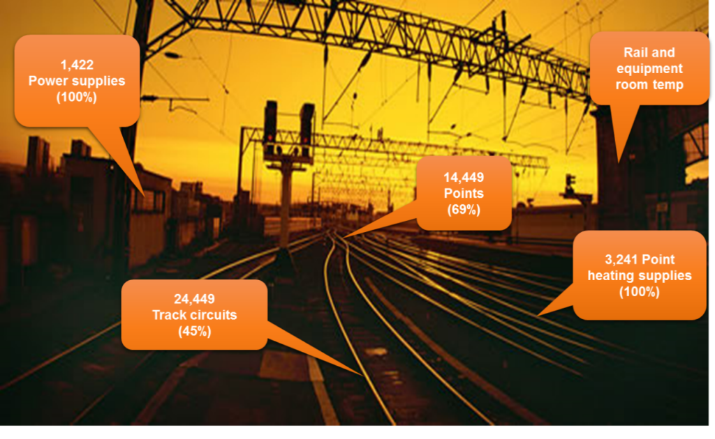
Embedded monitoring
Assets are fitted with sensors that monitor their condition, reporting back to a central system known as RADAR. This is monitored 24/7 by Intelligent Infrastructure technicians who use the information provided by the system to predict an asset failure, providing guidance to front line teams to help us to diagnose the likely failure mode and prevent the failure occurring. Use of this type of monitoring is widespread in Network Rail, as shown in the diagram below.
The introduction of Internet of Things devices will increase this footprint massively in the coming years, so research and development is focusing on how we can generate the best return on investment from the myriad of sensors that are now available.
Train-borne monitoring
Currently, there are two separate approaches to this, either having a dedicated set of infrastructure measurement trains or by fitting monitoring equipment to in-service vehicles.
The use of a dedicated measurement fleet is much more mature, and we now have 13 dedicated vehicles measuring the profile, depth and internal and external cracks in rails, the condition of the formation and geometry of the track, contact force and position of the overhead line, the loading gauge and quality of the radio signals.
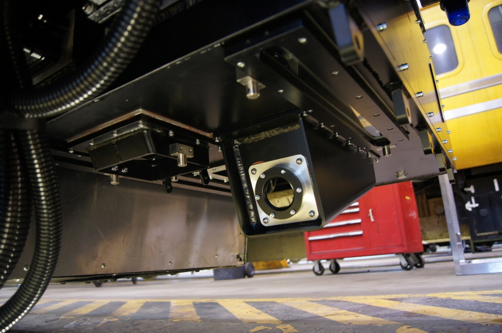
Assets already fitted with monitoring sensors.PLPR camera.
The most recent innovations in this area are:
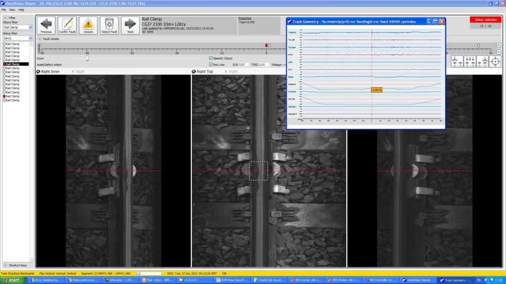
Plain-line pattern recognition (PLPR): With this system, pixel-width images of the track are recorded at up to 70,000 times per second across seven cameras. These images are integrated with laser profile and track geometry data and processed using machine vision to deliver defect reports to section managers, replacing the need to manually inspect plain line track. So far, this has been rolled out across approximately 9,000 miles of track, with a further 5,000 miles planned for the future.
Eddy-current inspection: Another replacement for manual inspection, this helps us understand the extent of cracking in the surface of a rail as the system is able to measure the depth of cracks rather than just their length. This system is now live across much of the network.
Switches and Crossing (S&C) Dynamic Measurement: Here, we run a specialist train through the S&C in both the normal and reverse position to give us a greater understanding of how it behaves under load.
Monitoring infrastructure using in-service trains is currently much less developed but has huge opportunities in the future to provide a near real-time indication of how the railway system is performing. Currently, several service trains have track geometry monitoring systems or accelerometers fitted and work is in development to utilise this data more completely in order to support maintenance activities. In 2020, a dynamic overhead line force measurement system will be fitted to an Avanti train on West Coast main line and work is progressing to fit similar systems onto East Coast and Great Western main lines.
PLPR screenshot.
One challenge that remains is the ability to predict driver-reported rough rides (DRRR). Drivers and traincrew are trained to report any suspicious vehicle movements to the control centre, in case there has been a sudden failure such as a rail break, track buckle or embankment failure which may pose a risk of derailment. This is a last line of defence because it is very unlikely that a sudden infrastructure failure will be picked up during routine asset measurement recordings, which only take place every four weeks.
The default response to a DRRR is to send a track maintenance team out to find what is wrong with the track and fix it. However, in most cases, and after many trains have been delayed, the maintenance intervention results in “No Fault Found”. We are launching a design contest to solve this issue, whilst also exploring the ability of smaller, simpler systems to give us an understanding of the track asset movement – without the need for full track geometry systems. It is expected that we will have prototypes in place and under trial within the next twelve months.
The ultimate aspiration from a train-borne measurement and monitoring perspective is to blend the right mix of dedicated measurement capability with in-service monitoring to ensure both safety and performance risks are mitigated.
Fixed monitoring
Network Rail has several fixed monitoring systems that are installed on the infrastructure and monitor trains as they pass. These measure axle bearing condition, using hot axle-box detectors (HABD), wheel condition using wheel impact load detectors (WILD) and pantograph condition using pantograph monitoring devices. The information generated from these systems is shared with train operators to help them improve their management of the condition of their vehicles. In the event of a serious defect being detected, operational rules are in place to mitigate safety risks, such as vehicle derailment due to rail breaks.
Network Rail is now working with TOCs and FOCs (train and freight operating companies) to understand how these systems can be rolled out further, to provide greater coverage, or enhanced, for example to included acoustic bearing monitoring.
This review is also considering whether there is a requirement for additional wheel lathes across the network to enable proactive wheel turning. It is expected that an improved average condition will not only extend wheel life but will also reduce wear and tear on the rail and ballast, improving the whole life cost of track – truly a whole industry benefit!
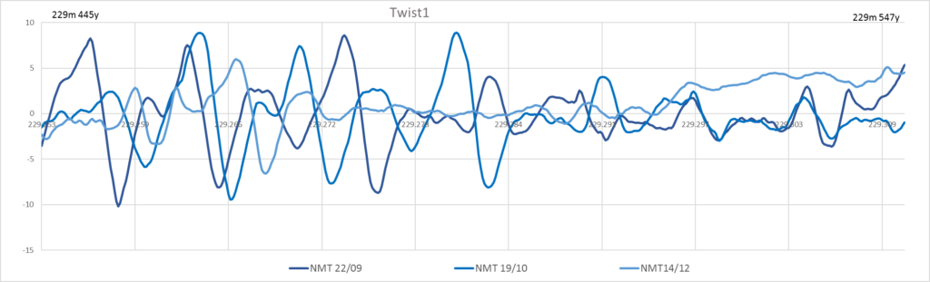
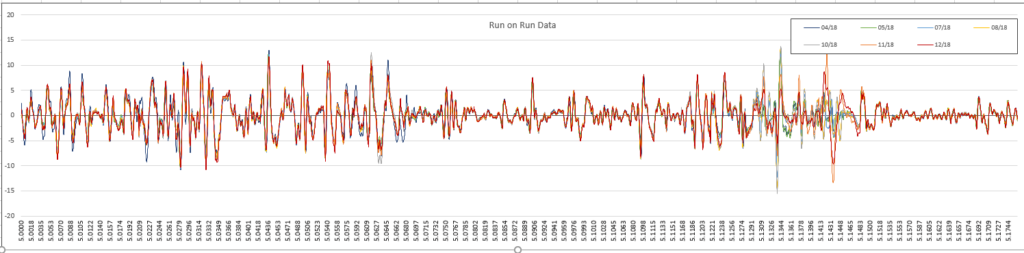
Twist measurement.Baseline.
Analytics
A huge amount of value will be derived from utilising advanced analytics and machine learning techniques to drive a greater understanding of asset condition and rates of degradation. These techniques, which will be applied across all asset systems, will use our existing data sources and also help us to understand what new data is required to drive efficiency and performance.
Initial delivery has concentrated on track and signalling, building on the decision support tools that we delivered as part of our ORBIS programme (issue 174, May 2019). For track, the initial challenge was to make sure the geometry measurement systems aligned across multiple runs to enable the degradation models to be as accurate as possible. The following diagram shows around 100 yards of twist measurements across three runs. Here the peaks and troughs of the measurements are offset between runs by approximately ten yards, making analysis difficult.
The teams have developed an algorithm that sets a baseline run and shifts all other runs to align to this baseline, as demonstrated in the above diagram, which shows seven runs over one mile, now in complete alignment.
The aligned data can then be used to predict when the track will degrade past alert and intervention limits, allowing intervention to be planned proactively.
Next to be delivered is cyclic top capability, which is being delivered in instalments. The first instalment will focus on a visualisation of the data to help maintenance teams get a better understanding of the nature and potential cause of the fault and how it might progress.
Future capability will begin to add predictive elements to the tool, showing the rate of degradation of cyclic top faults and highlighting any sites which are expected to become faults shortly. This will allow maintenance teams to plan their interventions earlier and treat a defect before it affects the service.
For signalling the teams are initially focusing on delivering diagnostic and predictive capability from the points and track circuit condition monitoring data. An example of how we are utilising the points data is below:
These are just some of the examples of analytics we plan to deploy as part of the programme. We have now mobilised the delivery teams and expect to be delivering capability across all disciplines from late 2020 onwards.
Visualising the railway
When Network Rail rolled out imagery and data from the first national aerial survey in 2016, it marked a major milestone in railway analysis and early project work that could be carried out from the safety of the office.
Using the Geo-RINM Viewer, planning and maintenance teams could carry out inspections, measurements and analysis of the railway without the need for manual inspections.
Desktop access to high-resolution images and 3D digital terrain and surface model data, the survey – carried out by the ORBIS programme – proved a resounding success. Routes were soon requesting updated data to keep pace with the changes taking place across the infrastructure.
To meet this demand the Intelligent Infrastructure programme was asked to develop and improve on the first survey. Working with Network Rail’s Air Operations team, new surveys were carried out over the past two winters – benefiting from reduced leaf and foliage cover to improve clarity of the network. This refreshed data is now being rolled out to the routes. Date labels and time sliders have been added to allow comparisons between old and new imagery so that accurate earthwork changes can be measured and changes to the infrastructure can be clearly seen.
Planning
Currently we use lots of different planning tools that have been developed by different routes, which means planning is inconsistent across Network Rail. The tools have been developed by local experts, which means that, while they are fit for purpose, they aren’t supported by our IT department. As a result, they often require a lot of ‘handle turning’ to update their core information and they can’t talk to other systems. This means that allocating people, materials and equipment to deliver the work in the access available is difficult and time consuming.
The planning workstream has therefore been scoped to create a new common set of planning tools holding information on the whole network. These will be supported by Route Services Information Technology (RSIT) and Asset Information Services (AIS), which can be adapted to suit different routes and regions as they choose.
There are three main outputs to this work:
Asset Lifecycle Planning System: This will help to manage the long and short-term workbank, helping to optimise maintenance and renewals work efficiently and effectively.
Work Planning and Scheduling System: This new scheduling system will take information from across the whole network and create schedules, taking into account unplanned work, asset conditions, criticality, best access times, resource available, materials and equipment. Work schedules will become more stabilised. This will help make plans more stable in the long term, allowing for work to be planned in a safer manner.
Time Recording System: This will accurately record the time Network Rail staff have spent at work against various activities, reducing administration and helping managers to understand the true unit cost of a job.
Execution
We have already deployed handheld devices to our frontline teams and supported management and engineering staff. To date, Network Rail has launched over 60 ‘apps’ to help our teams deliver effectively and efficiently, and all our analytics capability will be mobile device compatible.
In late 2020, we will make our condition monitoring trace information available to our faulting and maintenance teams, enabling them to check in real time that their activity has delivered the planned output.
The next steps will be to bring all our disparate data sources into an application that gives all the applicable information about a particular asset to our teams to enable them to pinpoint faulting activity, enabling a faster fix. The teams will be able to update this information on site with measurements or asset information, which will then be used to drive analytics improvements.
The goal with all our mobile capability is to provide the end user with a quality interface that is simple to use, intuitive, provides them with the information they require and only asks for input where it is absolutely necessary. In this respect, there is room for improvement with a lot of our apps, and we will be working closely with end users to give them what they need.
Delivering at pace
We have, wherever possible, introduced an agile methodology to deliver incremental capability, obtaining regular feedback from end users to drive future development.
By delivering something that users can both use and provide feedback on immediately, we are able to iterate through the development cycle every two weeks to quickly deliver an end product that meets all of their needs. Previously, it has taken up to two years from requirements gathering to an end user seeing a product, now it can be as little as two months for a first release!
We are starting to see the first benefits of the new way of working. More consistent and connected data will enable us to make earlier and better decisions that will result in a safer and more reliable infrastructure, both reducing our expenditure on emergency repairs and giving our customers and passengers a more reliable service – all through Intelligent Infrastructure.
Digital Surface Model (Hillshade) created from LiDAR data acquired in Winter 2018.
Relec Electronics has released the fourth generation of Mornsun’s R4 Series DC-DC converters in ultra-miniature DFN (dual-flat-no-lead) packages. Measuring just 9.0 x 7.0 x 3.1mm, they are available as non-isolated switching regulators or unregulated DC-DC converters with 3kV isolation.
Ideal for applications such as control, instrumentation and electric power, the ultra-miniature, surface-mount converters can save nearly 60 per cent of board space, occupying just 63mm² , compared to 155mm² for SMD8 footprint DC-DC converters. This enables developers to make significant space savings and reduce the overall size of distributed power supply systems, low frequency analogue circuits, industrial control, instrumentation and electric power products.
The R4 Series comprises the K78_MT-500R4 non-isolated switching regulators and the B0505MT-1WR4 – a 1W isolated DC-DC converter.
K78_MT-500R4 switching regulators provide 500mA or regulated power and are available with outputs from 3.3V – 15Vdc from a 4.5V – 36Vdc input source. With efficiencies of up to 92 per cent, they allow systems to run cooler without the need for external heatsinks. This not only reduces cost and saves board space, it also increases reliability by running at reduced temperatures.
The B0505MT-1WR4 is a 1W DC-DC converter with a 5Vdc input and 5Vdc output. It operates over an ambient temperature range of -40°C to +125°C and achieves an exceptional 3000Vdc isolation in the ultra-miniature DFN package. Efficiency is up to 85 per cent and no heatsink is required, making the device particularly suitable for use in applications such as digital circuits, low frequency analogue circuits, relay-driven circuits and data switching circuits.
The Mornsun R4 Series is available on a standard lead time of four weeks and Relec Electronics carries sample stocks to support your design effort and will work with customers to meet production requirements.
A report commissioned by Network Rail which looked into the future of railway station design has been published by Design Council. ThinkStation provides a framework for the future design of local stations following a wide-reaching engagement exercise completed earlier this year.
There are currently 2,000 small-to-medium local stations (categories D, E and F) in Great Britain, making up around 80 per cent of Network Rail’s station ownership.
Design Council organised 11 workshops, with 324 attendees from 120 organisations, in four major British cities. Its findings put forward priorities for designing a passenger hub of the future, next steps for using this learning and wider strategic advice for Network Rail and the rail industry.
The nine priorities that will guide the future design, development and procurement of local stations are:
Support existing and new communities in their local area
Reflect and embody local character and heritage
Provide consistent quality of space and service
Establish connections with and between the town centre and/or the high street
Celebrate, improve the quality of and/or provide access to green and open spaces
Be welcoming and facilitate inclusive travel
Support and better integrate cross modal transport
Help to address climate change
Ensure longevity by accommodating changes of use, capacity and trends
Sue Morgan, director of architecture and built environment at Design Council, said: “Better stations will improve millions of people’s lives and boost the quality of surrounding spaces through economic renewal, social enhancement and environmental restoration.
“Most of us would naturally accept these themes as priorities already, but this report demonstrates a clear evidence base, sets out ideas for bringing them forward and establishes Network Rail’s expectation that each one of them is a priority that will be present in future plans for all local stations.
“The rail industry is right to keep championing good design and applying design thinking when facing strategic opportunities and challenges, but it is hard. Station design varies greatly, and improvements need resourcing, which is now more of a challenge than ever. But, long term, our stations need to give passengers a better experience and they need to make more substantial contributions to global issues, such as climate change, and local needs, such as high street vitality. This report makes the task clearer for everyone involved.”
Anthony Dewar, professional head of buildings and architecture at Network Rail, added: “We wanted to put passengers and stakeholders at the heart of the next generation of railway stations.
“The ambition here is to raise the quality of design across our network as well as responding to the evolving role of infrastructure within communities. 80 per cent of our stations need to be integrated into smaller urban and rural contexts and this report creates a framework that can then be made appropriate to each community and its needs.
“This report envisions stations that value communities, connectivity and stronger placemaking and we want to make that happen through the upcoming competition and across our portfolio.”
The ThinkStation report and its findings will inform the brief and judging for Network Rail’s international design competition for medium and small stations across Great Britain, as well as shaping future design work and further community engagement. The competition, which will be run by RIBA, will launch in July.
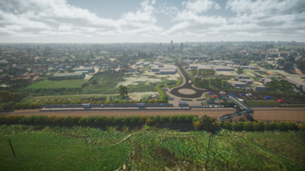
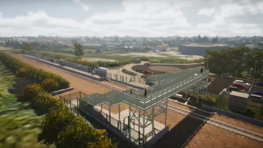
Network Rail can now proceed with starting the early enabling works this autumn. Cambridgeshire and Peterborough Combined Authority, led by Mayor James Palmer, is providing the necessary funding to build the station.
Reconnecting Soham to the rail network will be the realisation of a long campaign by the community to rebuild the station which was closed in the 1960s. A new station will provide residents and local businesses with better connections and support more investment as part of the Council’s vision for the wider area.
The new station at Soham will include:
Construction of a single 99 metre platform to accommodate four car train services including waiting shelters, lighting, information screens and a public address system;
Installation of a stepped footbridge across the railway to connect to an existing public right of way, designed for any future installation of lifts for a potential second platform for any scheme;
Construction of a drop off point and a car park to accommodate 50 vehicles and five spaces for blue badge holders, as well as lighting masts;
Cycle parking and ticket vending machines on the station forecourt.
The main construction phase is planned to start in 2021 with completion date expected in spring 2022. Greater Anglia services will start to call at the new station shortly afterward.
Ellie Burrows, Network Rail’s route director for Anglia, said: “With the consent now confirmed, this will mark an important new chapter for Soham providing more choice for people to travel and offering better connectivity to regional destinations.
“I am thrilled that, working in partnership with the Combined Authority and Mayor James Palmer, we can now reconnect Soham to the rail network which will deliver significant benefits for the local community when complete.”
One of the winners of the Department for Transport’s 2020 First of a Kind (FOAK) competition has been announced as being Unipart Rail, which won in the Environmental Sustainability category.
The DfT organised the competition in partnership with Innovate UK, which is awarding funding to innovative projects that will make railways cleaner, greener and more passenger friendly. 25 pioneering projects will each receive a share of £9.4 million to help develop their new products.
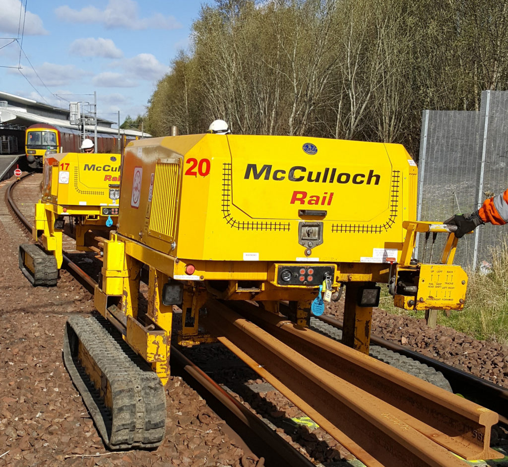
Unipart, working with McCulloch Rail, Hyperbat, Williams Advanced Engineering and Advanced Electric Machines, is developing the ‘TRT-e’ – a zero emissions Trac Rail Transposer based on the McCulloch Rail TRT machines, the safest, most versatile rail handling machine on the rail infrastructure.
For the new zero-emissions machine, Unipart Rail and its partners will work together to remove the current diesel power unit and develop an electric motor, battery power pack and electronic control system with remote condition monitoring. This will enable it to be used on the rail infrastructure where diesel emissions and noise pollution are a particular problem, for example in underground systems, tunnels and enclosed stations.
McColloch TRT.
The output of this project will be a full working prototype, performance-tested, certified and ready to be worked on the UK rail network by McCulloch Rail and demonstrated to potential customers worldwide.
Entering this First of a Kind competition gave Unipart Rail the opportunity to work with world-leading experts in the field of electric-powered vehicles to develop a zero-emissions demonstrator of the already successful and proven TRT that will enhance the working environment and experience of contractors working with the machines.
Noel Travers, managing director of Unipart Rail and Unipart Manufacturing Group, said: “Our partnership with McCulloch Rail is one I am very proud of – their technology is transforming rail handling methods, and this is an example of how joint innovative thinking drives massive value for the rail industry.
“I am very excited to see this development happen and look forward to the product launch in 2021, when I expect it to have a strong uptake with our customers.”
Billy McCulloch, engineering director McCulloch Rail said “The TRT is already a great product – the development of the fully electric version will be a big step forward in the world of lifting and handling, and we are excited to develop this first-of-its-kind technology for the rail industry.”
In this series so far, Rail Engineer has reported on the tests of Double Variable Rate Sanders (DVRS – a new acronym is born) on a Class 387 Electrostar at the RIDC Melton (issue 157, November 2017), the encouraging results of those trials (issue 163, May 2018) and driver-familiarisation runs on Class 323 units from the Birmingham Cross City line (issue 179, November 2019). If, dear reader, you have detected a pattern, you will be expecting to see a report of the results of those trials – you will not be disappointed!
RSSB, which has sponsored all this work with the support and cooperation of many other organisations, had set up two dissemination events for late March and early April 2020, but due to the national Coronavirus emergency, the events were transferred to webinars, and this is your writer’s first ever report of a webinar!
It was also the first webinar to hold his attention for the whole event, but that’s another matter!
Congratulations to Giulia Lorenzini for organising the technology and to the speakers for mastering the remote presentation technique with little notice.
In-service pilot, option selection
Rail Engineer’s report on the results of the 2017 tests (issue 163, May 2018) signed off with the comment: “The next steps are to implement the results with pace and passion; a significant challenge.” A number of train-operating companies approached RSSB volunteering parts of their fleets to act as host for a service trial (see panel for the list of fleets considered).
Liam Purcell, principal consultant from Ricardo, outlined the process used to select the trial fleet/operator. Feasibility studies were carried out for each fleet covering technical factors such as space, structure for attachment of sand hoppers, whether the electrical and air supplies were sufficient, and the ability to connect to the various controls, such as wheel-slide protection (WSP).
The nature of the operation was also considered, including the route and whether there were already pre-existing performance/adhesion concerns.
Candidate fleets considered for the in-service trial:
Class 444 (South West Railway)
Class 172 (West Midlands Trains)
Class 323 (West Midlands Trains)
Class 318 (ScotRail)
Class 320 (ScotRail)
Class 334 (ScotRail)
Class 380 (ScotRail)
Class 321 (Greater Anglia)
Class 170 (Northern Rail)
The studies showed that it was feasible to fit DVRS to all the candidate fleets, but the West Midlands Trains’ (WMT) Class 323 was chosen because the Birmingham Cross City line is known to suffer autumn adhesion issues and the installation and interface were comparatively challenging.
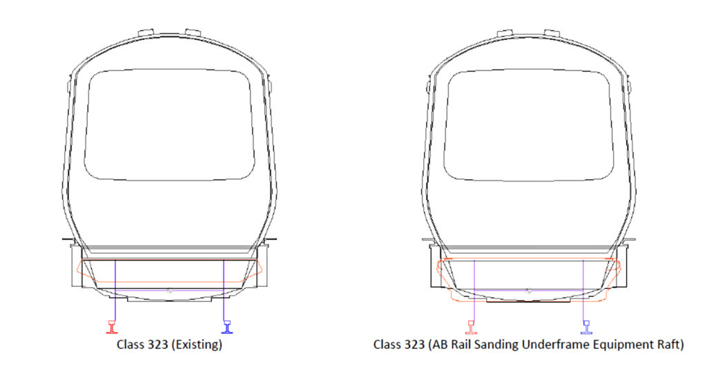
Three key issues affected the installation: limited space to install the sanders on the intermediate vehicle of the three-car units, potential inhibition of return current caused by additional sand and limited availability of spare units for DVRS fitment.
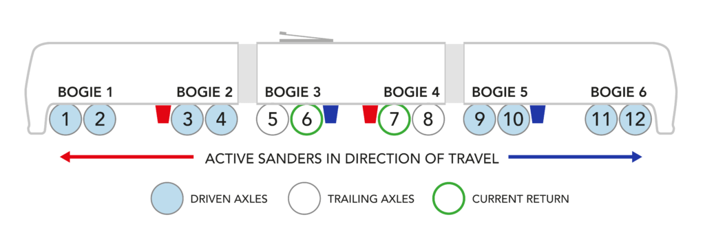
Layout of sanders and bogie/axle numbers.
Return current
The return-current issue had been identified in the planning for the 2017 tests but was managed as a risk at the time. For this work, the issue had to be resolved. On the Class 323, the primary traction-return axles are numbers 6 and 7 – the inner axles in the intermediate pantograph trailer car.
These are also the axles where the additional sanders were to be located, so there was concern that the extra sand might affect the traction return path.
A practical instrumented test was developed, the first stage of which involved manually applying sand to the running rail and running bogie 4 over it. Bogie 3 has a slightly shorter current path through its cable than bogie 4, so more current flows that way, making bogie 4 the worst case.
The test demonstrated that current was transferred from bogie 4 to bogie 3 as a result of the sand but remained via the traction return axles, so sand was applied manually under both bogies. The level of current returned via alternative paths (not through bogies 3 and 4) was measured with sanding up to 8g/m (above the 7.5g/m limit), current continued to be returned to the running rails via bogies 3 and 4, with rapid deterioration as the sand deposition increased further; a successful test.
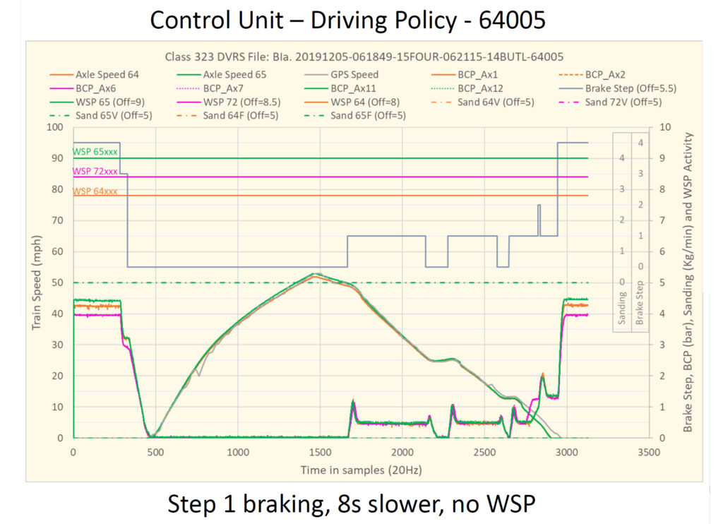
In order to monitor performance of the brakes and the sanding systems, equipment to allow remote condition monitoring (RCM) was installed on both the DVRS units and four unmodified “control” units. This equipment monitors a number of channels at 20Hz (see list) which worked continuously through autumn 2019.
Remote Condition Monitoring Instrumented Systems:
GPS Speed
GPS Location
Brake Cylinder Pressures (x 6)
Brake Step
Main Reservoir Pressure (x 2)
ED Brake Achieved (x 2)
Direction (x 2)
Acceleration
WSP Activity (x 3)
Sanding Activity (x 4)
Sand Level (x 3)
Low Sand Alarm (x 3)
Cab Speedometer (x 2)
Cab Active (x 2)
Doors Open (x 2)
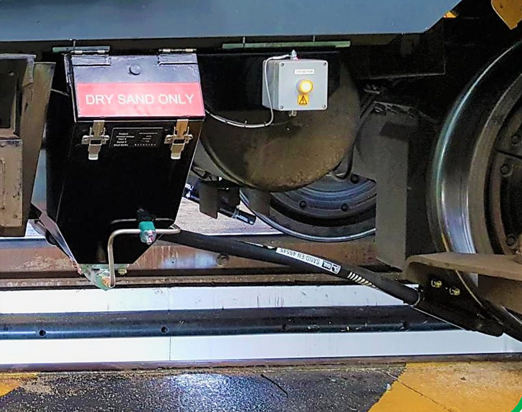
Increased size of DVRS hoppers (right, red outline).
It had been intended to complete the installation for autumn 2018, but the challenges of fitting sophisticated equipment to older trains reared their ugly heads, including noise on the WSP channels, interference on speedometer and door signals, and spurious tripping of circuit breakers.
Class 323 installation
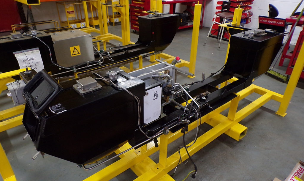
Mick Milhinch, engineering director of AB Rail, part of AB Hoses & Fittings, explained the design and fitment of the DVRS. Mick described his company as the “one stop shop” for all sander system needs. Its Advanced Automatic Sander is a computer-controlled system which is capable of taking any input or logic from the train and configuring those inputs to provide the required sander operation and delivery rate. This is based on two CPUs (central processing units).
CPU 1 (the brains of the system) interfaces with and is mounted on the train – it communicates with CPU 2, which is mounted on the sander raft and controls the sanders. One CPU 1 can control two sander-system rafts (as is the case on the intermediate car). The system is equipped with a data logger, GPS, 4G and Wi-Fi. For the trial, it was interfaced with the RCM system described by Liam.
The mechanical parts are all mounted on a raft that fits across the width of the underframe.
Mick said one of the key requirements was to keep the sand dry, and it was decided to double the size of the hoppers to a capacity of approximately 60kg even though sand consumption was not expected to increase. Higher capacity and a sensor to advise sand levels all contribute to reducing the need to open the hopper, helping to keep the sand dry. This did mean pushing the gauge and structural limits.
Mick added that all the efforts to keep the sand dry will come to naught if the air supply is contaminated, adding: “However good you think the train air supply quality is, or are told it is, it won’t be good enough.” Needless to say, the new sander raft incorporates an air filter and dryer.
Sander Raft showing CPU 2.Fried electronics.
There was little space available on the intermediate vehicle to install a raft, so a custom design was developed that, for standardisation, was also used on the end vehicles.
The intent was to base the new designs on the excellent original drawings, until the following note was found on the drawing which, putting it politely, sounded a note of caution: “Method of hopper construction to be at the discretion of the fabricator”.
In practice, the existing hoppers deviated significantly from the drawing and the CAD (computer-aided design) model had to be created from scratch, with much double and triple-checking that the vehicles actually conformed to the dimensions on other original drawings.
Installation was also a challenge, simply because of fleet utilisation, but this was overcome by kitting, bespoke transportation, storage and installation equipment pit boards, stillages, skates, lifting frames, jacks etc. and by breaking installation down into discrete packages.
Following installation of each package, the train could go back into service with original sanders still fitted and working until DVRS rafts were installed last of all.
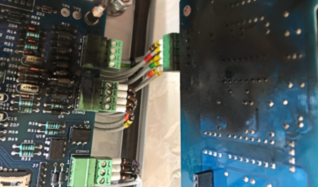
Mick described another unexpected problem, as all four CPU 1 units were exposed to significant over-voltage between the brake 0V and brake-step wires.
These had been designed to cope with 165V on the normal 110V supply, which conforms with EN 50155 and, in AB Hoses previous experience, such protection had been satisfactory. No explanation for the phenomenon was found but the over-voltage protection was increased to 600V and there has been no more trouble. As Mick put it: “Over voltage is believed to be a normal operating characteristic of the class 323 fleet.”
Mick summarised the lessons learned:
Be very, very, very cautious when using historical drawings; trust nothing unless you’ve checked it for yourself against the real thing;
Rafts/hoppers can be made to fit just about anywhere but this needs thought and careful design;
It is possible to install DVRS in and around a normal running and maintenance regime and a full train can be installed between peaks/overnight;
Don’t assume the train works as expected when it comes to interfacing existing and new systems just because the train isn’t failing now – gather real data before designing or else over-engineer!
He also identified two issues that might apply to other fleets. Firstly, the speed signal needs to be accessed for the DVRS system and doing so on an existing vehicle might involve risking the performance of existing train speed signals. He said that AB Hoses is working on a doppler radar speedometer to be incorporated into the raft.
Secondly, it is often necessary to get signals from inside the vehicle end cubicle to the underframe and thence to the rafts where the wiring does not exist and, whilst precedent was set on the Class 323 for using flexible conduit and drilling holes in body end and underframe equipment case, this might not be an option on some of the other classes assessed. He said that his company is working on “power line communication technology”.
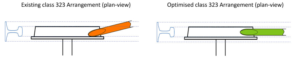
Mick also pointed out the importance of the sand delivery hose alignment. For some reason – lost in the mists of time – the Class 323 delivery hoses had been aligned to fire sand in the direction of the tread/flange area and most of the sand was falling on the ballast. This was noticed but had been assumed to be satisfactory because it had been in service for so long. However, results in commissioning were poor and the hoses were realigned, after which the expected performance was delivered – another lesson in not taking anything for granted!
Mick’s parting shot was “It’s all about the sand! All of the clever design and application comes to naught if the sand isn’t clean, dry and in the nip!”
Sand delivery nozzle alignment, original (left), modified (right).
Train braking
While some modern multiple unit trains have infinitely variable braking, older multiple units have three (or sometimes four) braking ‘steps’. Step 1 is a light brake application, step 2 is a harder application of the brakes, and step 3 is the full-service brake. There can also be a higher-rate emergency brake, used, for example, when an obstruction is seen on the line. Sanding is enabled in steps 2 and 3.
The effectiveness of each step is measured in the deceleration of the train. There are two ways of presenting this – either actual deceleration in metres per second squared (m/s²) or as a percentage of the normal acceleration (or deceleration) due to gravity. This is 9.81 metres per second squared (9.81 m/s²) (32 feet per second per second in old units), so a deceleration of 10% g would be 0.981 m/s².
Each step is designed to deliver at least a defined performance on level dry track and, for example, step 2 might be described as delivering 6% g. In practice, the actual performance depends on gradient, rail conditions, and wheel diameter.
Formula One motor racing fans will have heard commentators talking about the “g forces” that the drivers experience. With light weight, carbon fibre brakes, aerodynamics that promote downforce and wide sticky tyres that won’t slide, they can decelerate at up to five times g (5 g = 49.05 m/s²), compared with a conventional road car that can deliver, at best, 0.8-1.2 times g.
Trains on steel rails slide a lot more easily, so 13% g is generally the best they can achieve, given adhesion levels normally accepted, unless other techniques such as magnetic track brakes are fitted. After that, the wheels lock, the train slides, and deceleration actually decreases – as well as causing damage to the track.
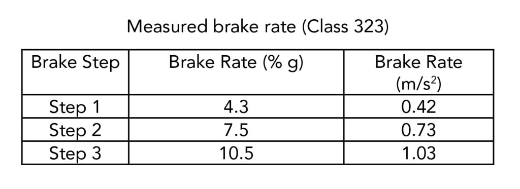
The Class 323 trains in these tests have the three steps plus emergency brake system and the actual results obtained during the tests were:
Measured brake rate (Class 323)
The results
Andrew Lightoller, principal mechanical engineer at DB ESG, continued the story.
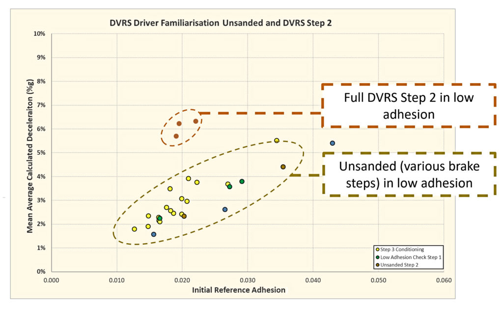
In October 2019, familiarisation runs were carried out on a section of the line just north of Redditch, as described in issue 179. This work was intended to demonstrate the system to WMT’s management and drivers and to give the latter the opportunity to experience DVRS in low adhesion conditions for themselves.
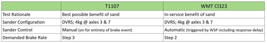
As a by-product, the team was able to evaluate the impact of DVRS controlled by the WSP, compared with the original trials at RIDC where the sanding was manually controlled.
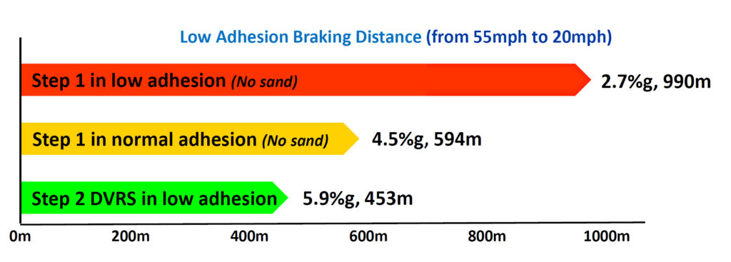
The results were impressive. Compared with unsanded operation in brake step 1 (nominal brake rate 4.2% g), where the achieved brake rate on very low adhesion was, on average, 2.7% g, DVRS operation on very low adhesion consistently achieved a step 2 brake rate around 6% g. This means that the braking distance was approximately halved. Even in low adhesion, Step 2 with DVRS provides a deceleration greater than the nominal step 1 brake performance, which is the assumed brake rate used in the spring and summer to meet the demands of the cross-city timetable.
As reported in issue 179, both drivers and management were impressed with the familiarisation runs and WMT was happy to use the system in service during the autumn season. Some 115,000 qualifying braking events were recorded on the DVRS and the ‘control’ units between October and mid-December 2019. Analysis showed that, of the total distance travelled whilst braking, 94% was under step 1 braking (without sand) and only approximately 5% was under step 2. The percentages were remarkably similar for both the DVRS and the control units.
This indicated that professional driving practices, which encourage step 1 braking, are deeply ingrained. With only five per cent of the braking being above step 1, and thus capable of deploying sand, it was recognised that driver technique needs to change to benefit from DVRS.
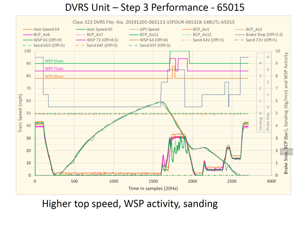
Andrew reported that WMT was keen to confirm benefits following the familiarisation runs. A back to back test run was therefore undertaken on 5 December 2019 – a leaf fall “amber” day – where the rail head looked damp but clean. Unit 323 205 (control) operated using the WMT’s professional driving policy and unit 323 215 (DVRS) operated using full braking capability. There was a single occurrence of wheelslide, but it was not significant.
It was notable that driver confidence in the DVRS was such that the train would typically be driven to a higher maximum speed. This, together with the step 3 brake, delivered a run time improvement of approximately eight seconds between stations.
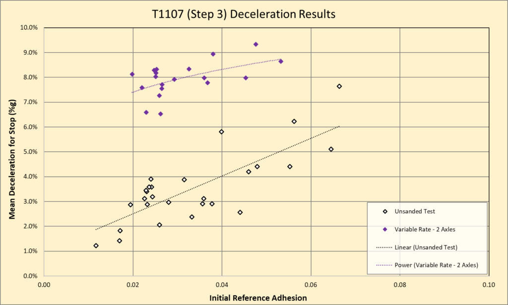
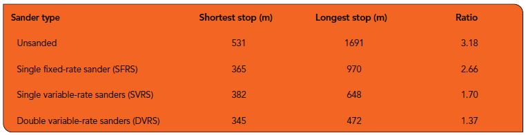
After the presentations, Andrew commented that another benefit of the sanders, whether single variable-rate sanders (SVRS) or DVRS, is in the consistency of low adhesion stops. Referring back to the 2017 trials, the longest stopping distance experienced from 55mph for unsanded low adhesion runs was over three times the shortest. Whereas for DVRS the longest was just 37% higher with other configurations in between, as seen in the illustration and table – see below.
Moreover, the longest stopping distance for DVRS was shorter than the shortest unsanded run.
In summary, this has been a further validation of the benefits of DVRS. A middle-aged train equipped with DVRS delivered performance at least as good as the original sander tests in 2017 and there has been very positive feedback from train drivers. There does need to be a review of professional driving policies to gain the full benefit of DVRS and RSSB is working on this with its partners.
Rail Engineer looks forward to further developments.
Thanks to Paul Gray, Aaron Barrett, and Emma Bassey, RSSB, and the speakers mentioned for their assistance in producing this article
Merseyrail is the commuter rail network serving Liverpool and is one of the most heavily used urban railway networks outside London. It consists of two dedicated DC third-rail electrified lines known as the Northern line and Wirral line, creating a metro-style network of local passenger rail services within Merseyside and adjacent areas of Cheshire and Lancashire, including a number of underground stations.
A number of organisations are involved. Merseyrail is the operator, currently run by Serco-Abellio under a contract which runs until 2028. Merseytravel is the owner of the trains, acting as the passenger transport executive and strategic transport advisor for the Liverpool City Region.
Over the years, Merseyrail has pioneered a number of control and communications initiatives and is currently rolling out new ‘connected’ trains.
The network normally carries 110,000 passengers on weekdays and a total of 34 million passengers per year along its 75 miles of route with 68 stations. Six stations and 6.5 miles of route are underground. It can be a surprise to some visitors arriving at Liverpool Lime Street main station to find ‘full size’ trains entering the underground platform every few minutes.
The Northern line links underground stations at Liverpool Central and Moorfields with Southport, Ormskirk, Kirkby and Hunts Cross, while the Wirral line ‘loop’ links underground stations at James Street, Moorfields, Lime Street and Liverpool Central with Hamilton Square the other side of the Mersey River and on to Chester, Ellesmere Port, New Brighton and West Kirby.
Conway Park station was opened in 1998 to provide a station more convenient for the town centre of Birkenhead than either Birkenhead Park or Hamilton Square, but it doesn’t have “Birkenhead” in its name and can be mistaken for Conwy station in North Wales. Conway Park was built by excavating a box downwards, opening out the roof of the tunnel, and is 18 metres (59ft) below ground level. Even though it is below ground level, it is not subject to the Fire Precautions (Sub-surface Railway Stations) Regulations due to its open construction.
The network currently operates a fleet of 59 Class 507 and Class 508 three-car electric multiple unit trains. These were constructed in the late 70s and are in the process of being replaced by a fleet of 52 (with an option for 60 more) new Class 777 custom-built train sets made specifically for the Merseyrail network by Stadler Rail. Interestingly, the trains are being financed by Liverpool City Region itself, rather than by a bank or leasing company.
Sandhills IECC
The Merseyrail network is predominantly signalled from an integrated electronic control centre (IECC) located near to Sandhills station to the north of the city and called Sandhills IECC. The IECC controls a Remote Relay Interlocking (RRI) at Rock Ferry for part of the Wirral Line, with Solid State Interlocking (SSI) for the rest of the Sandhills control area.
The IECC has two signalling positions. One for the Northern Lines and one for the Wirral Lines, two separate CCTV crossing keeper positions and an electric control operator for the DC traction supply.
While making Merseyrail a completely independent, ‘vertically integrated’ railway has been proposed in the past, one of the problems with this proposal is that the IECC signalling arrangements are not unique to Merseyrail and the IECC does not control all of the Merseyrail network. The IECC also controls part of the Manchester to Southport line nearer the Southport end of the route, together with the Borderlands line between Bidston and Dee Marsh Junction. Between Brunswick and Hunts Cross, the Northern line is signalled from Hunts Cross Power Signal Box (PSB) and south of Hooton railway station the Wirral line is signalled from Chester PSB.
Both Hunts Cross and Chester PSBs control other parts of the national network and extensive resignalling would be required to make Merseyrail signalling self-contained.
The separate CCTV crossing positions in the IECC are required for the large number of CCTV-monitored crossings on the Northern line, which are too many for a signaller to monitor and control.
The IECC also has a separate operational control facility within the building. This is for train service management, incident management, operational people resources, fleet planning and maintenance, customer information, underground fire detection, public address and the monitoring of help points – all assisted by a comprehensive CCTV system.
In addition to individual CCTV monitors for each operator, there is a CCTV video wall with 32 flat screen monitors. There is also an automatic camera viewing link so that, in the event of an automatic fire alarm activation in the underground, assigned CCTV cameras for a particular alarm area will be automatically activated on the video wall.
The CCTV system was originally provided in the 70s for the five sub-surface stations, with black and white pictures and monitored from a control room at Moorfields. Only certain cameras were fitted with zoom lenses. Following the King Cross Fire in 1987 and the subsequent Fire Precautions (Sub-surface Railway Stations) Regulations 1989, the CCTV was upgraded to colour and with more cameras featuring pan, tilt and zoom, along with fire resistant cabling.
Automatic fire detection with integrated public address was also provided and, when control was transferred to the IECC in 1993, additional surface stations were connected to the system.
Over the years the CCTV system has been expanded and upgraded, so that today the system monitors an impressive 70 stations and depots with over 1,000 cameras. It does not stop there, as over the next two years many of the cameras will be upgraded to all IP (internet protocol) types. Telent is the designer for the upgrade.
To comply with the sub-surface fire regulations in 1994, a comprehensive radio system was also installed to operate in all parts of the underground, including stations and running tunnels. Radio channels were provided for the then VHF National Radio Network (NRN), British Transport Police (BTP), Fire Authority and UHF Cab Secure Radio (CSR) to enable all trains to communicate with signallers.
The CSR system was also provided with radio masts on the above-ground parts of the network to facilitate 100 per cent train to signaller radio coverage. The functionality of the system was very similar to today’s GSM-R system, only it was provided years before the latter was conceived.
The BTP VHF channel was replaced with the Tetra Airwave System in the 1990s and the BTP VHF frequencies re-licensed for railway use – all operating over the same ‘leaky’ feeder infrastructure. The CSR system has now been replaced by GSM-R, with its own unique leaky feeder.
New trains and Wi-Fi
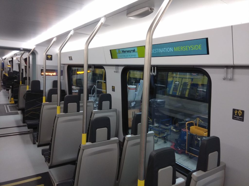
The current 507/508 fleet, despite being one of the oldest on the network, appear surprisingly modern with a reasonable ride, good visibility and comfortable seats. The units have lasted well, as they were last refurbished 17 years ago when they were provided with new high-backed seating, interior panels, lighting, and a passenger information system.
However, the new trains will be even better and are ‘state of the art’ articulated four-car units, with 50 per cent higher capacity and faster acceleration and deceleration to reduce journey times by up to 10 per cent. They are also 5.5 tonnes lighter, with more efficient electrical systems, and so use 20 per cent less energy. They will feature free Wi-Fi, including coverage in tunnels and underground stations, along with high-quality CCTV and voice links between the trains and Merseyrail’s control centre in Sandhills IECC. The system will also provide data on the exact number of passengers on each train to enable better management of the network.
The Class 777 is a new design, specific to the Merseyrail network. The two longer driving cars at each end will only have one set of twin doors on each side, while the two middle trailer cars will have two sets. The trains will also have sliding steps as ‘gap fillers’ between the train and the platform, which will mean passengers using a wheelchair will not have to use a ramp when boarding, improving accessibility for all users.
Each train will also be provided with power and USB sockets and bike racks. Instead of having partition doors between each carriage, the articulated units form one large open space. Like the current Class 507 and 508 trains, the Class 777s will not be provided with toilets as journeys are considered to be too short to warrant them.
As well as providing improved passenger facilities, the new trains are future-proofed by having dual-voltage capability (25kV AC overhead supply as well as DC third rail). This could possibly allow them to operate beyond the third-rail DC electrification infrastructure to destinations such as Helsby, Preston, Skelmersdale, Warrington and Wrexham, as any future extension of the third rail traction system in unlikely to be approved due to the risk to people on the track.
The trains will also be fitted with small battery sets, for easy movement around workshops and depots. It could also permit them to move to the next station in the event of a traction power failure, but this would depend on the distance as it isn’t the prime aim of this feature.
As has been mentioned, the trains are being provided by a self-financing, sustainable business model with no rolling stock company or rolling stock leasing company involved. This is a natural extension of devolution and will deliver savings in energy, maintenance and operations plus additional revenues flow to Merseytravel, which will become the UK’s only public-sector mainline rolling-stock owner.
It has also been decided to contract maintenance for the new fleet, so the deal for the new trains with Stadler includes modernisation of the train maintenance depots at Kikdale and Birkenhead North, along with the provision of a new driving-cab simulator.
Steve Rotheram, Metro Mayor of the Liverpool City Region, said: “We are investing nearly half a billion pounds in a new, publicly-owned fleet for the Merseyrail network and the infrastructure it will run on. This will increase capacity, reduce travel times and provide a better experience for the travelling public. Our new fleet will be one of the best connected in the world, which not only means that people can use their smart phones or tablets via Wi-Fi, it also means a safer and more responsive network.”
Infrastructure works
Extensive platform adjustments and track realignments have been required to accommodate the new trains and their sliding steps that improve passenger accessibility. The work has taken place on 97 platforms at 56 stations across the Merseyrail network using a rolling programme between October 2018 and May 2019. The programme was designed to minimise disruption to passengers wherever possible.
The existing trains Class 507/508 trains are 60.7 metres long for a three-car unit and 121.4 metres for a six-car unit. The new trains are longer – 65 metres for a four-car unit and 130 metres for an eight-car – with a 50 per cent passenger capacity increase, so platform lengthening, signal moves and track lengthening in the reversing siding at Liverpool Central have also been required.
The Class 777 trains will deliver a 10 per cent journey time reduction partly through improved acceleration, so they will require a more reliable traction power infrastructure to address voltage drop and increase current from 4kA to 5.4kA. Three new bulk supply points are being provided by Scottish Power, along with eight new substations and extensive cable upgrades.
New high-capacity Wi-Fi
Panasonic is providing an extensive new trackside network-wide Wi-Fi system. This will provide 100Mbps data connectivity to all trains and will enable high-quality, real time CCTV, voice and data links between the trains and the Sandhills control centre. This impressive initiative, which will also provide free internet access for passengers, is known as the Merseytravel Train Connectivity and Information System (TCIS).
There are several elements forming the TCIS:
The Optical Fibre Network (OFN): This will provide full system connectivity across the Merseyrail network, achieved by installing a 432-fibre optic cable providing full fibre connectivity linking the new equipment within the Sandhills control room to all the station and trackside access points across the TCIS network.
Trackside radio: The full coverage will be achieved by strategically located eight-metre tilt monopole mast antenna/access points at station and trackside locations, to assure that there are no signal drop zones and the trains are in constant communications with the station and trackside access points.
On-Board radio: A mobile radio unit will be installed at each end of the train. All data traffic to and from the train will go via an on-board router for the purpose of network monitoring and to restrict access to trusted users only.
Ethernet network: The managed Ethernet network will provide a 1Gbps managed link between each mast site and the nearest station. This will give provision for a chain of ten access sites on a single 10G circuit, providing remote management for each access site along with spare switch capacity for future expansion.
The revisions to the existing Merseyrail operations in Sandhills IECC will consist of a single TCIS workstation on each of the existing and proposed operator work positions and two 49-inch monitors with a multi view option for viewing six to eight cameras on one screen.
Best performing operator
Merseyrail has been amongst the top best-performing train operators for many years, winning the ‘best-performing regional rail operator’ award at the 2019 Golden Whistle Awards, with 96 per cent of trains running on time.
It was also named ‘most punctual operator’ in 2019 and came top in the national rail passenger survey for Autumn 2019.
The new Class 777 trains, with their state-of-the-art facilities, performance and communications, can only drive further improvements for Merseyrail’s customers.