

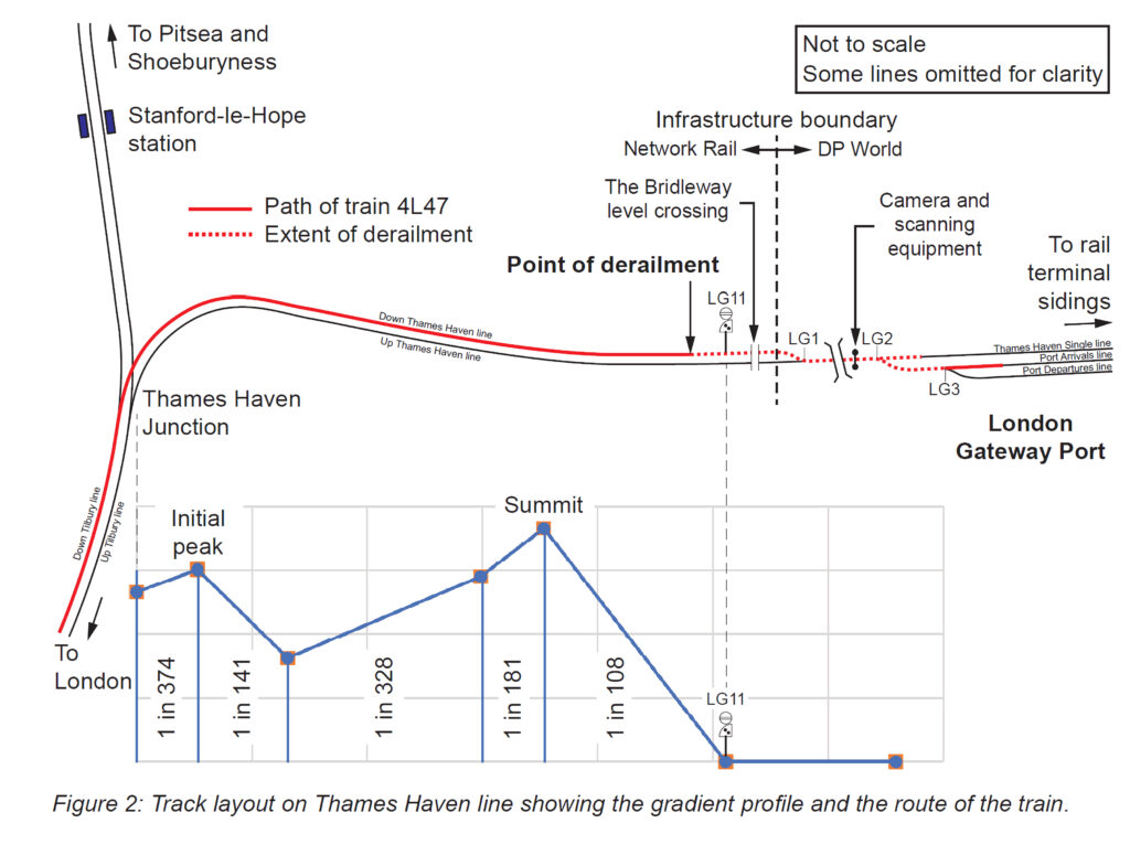
“At around 05:45 hrs on 24 December 2021, five wagons of a 33-wagon intermodal freight train derailed at low speed as the train was entering the rail terminal at London Gateway port, Essex. The derailment started when wheels on a wagon in the middle part of the train suddenly lifted off the track, just before reaching the port boundary, with the other wagons becoming derailed as they passed over points within the rail terminal. While no one was injured, infrastructure damage disrupted rail freight access into and out of the port for 14 days.“
So said the RAIB in its December 2022 report into the derailment.
The RAIB’s inspectors must have been surprised to encounter a derailed freight train on a straight piece of track, with no apparent defects in cold but dry conditions. Although previous derailments provided some clues, there were also mysteries which led to some groundbreaking analysis and simulation. This article will discuss the investigation, modelling, and the parallels the RAIB drew from previous derailments and collisions.
Background
Freight train couplings
Freight trains typically comprise a locomotive and a number of wagons which are connected together with traditional spring buffers either side of the underframe, and a centre coupling hook and screw coupler. A typical traditional container wagon is about 65ft long and able to carry a 40ft and 20ft container. With the advent of taller containers, and the ever-increasing proportion of 40ft containers, freight operators sought suitable wagons which are both shorter and with a lower deck than is traditional.
If conventional buffers/screw couplings were to be used on all these shorter wagons, a great deal of available train length would be wasted as the buffers and coupler housings would have to be above deck level using space that could be occupied by a container. Instead, engineers developed designs for twin or triple wagons, where intermediate semi-permanent couplings, using centre drawbars with integral resilient elements to absorb buff and draw shocks (bar couplers), were provided with no side buffers. Twin wagons with one intermediate bar coupler came first, followed by triple wagons with two. It was the centre wagon of a three-wagon set – an FWA Ecofret 2 – that derailed first at London Gateway. This wagon was in the centre of the train and was not loaded.
FWA – Ecofret wagons
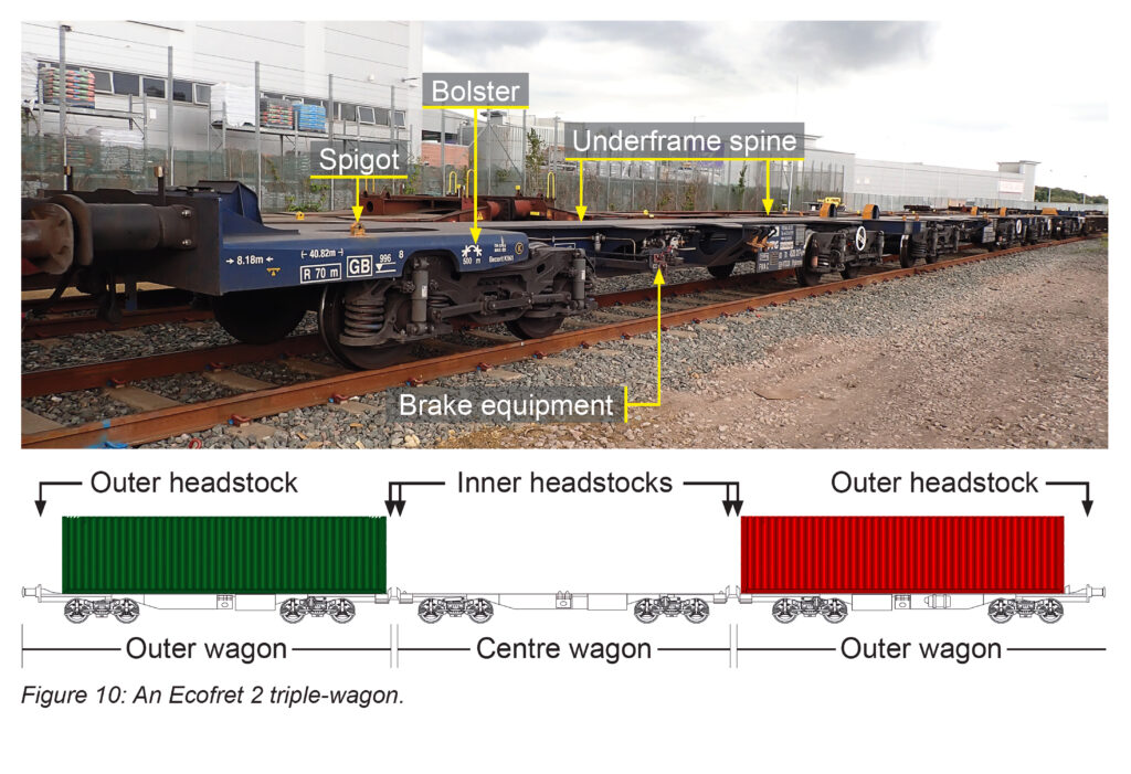
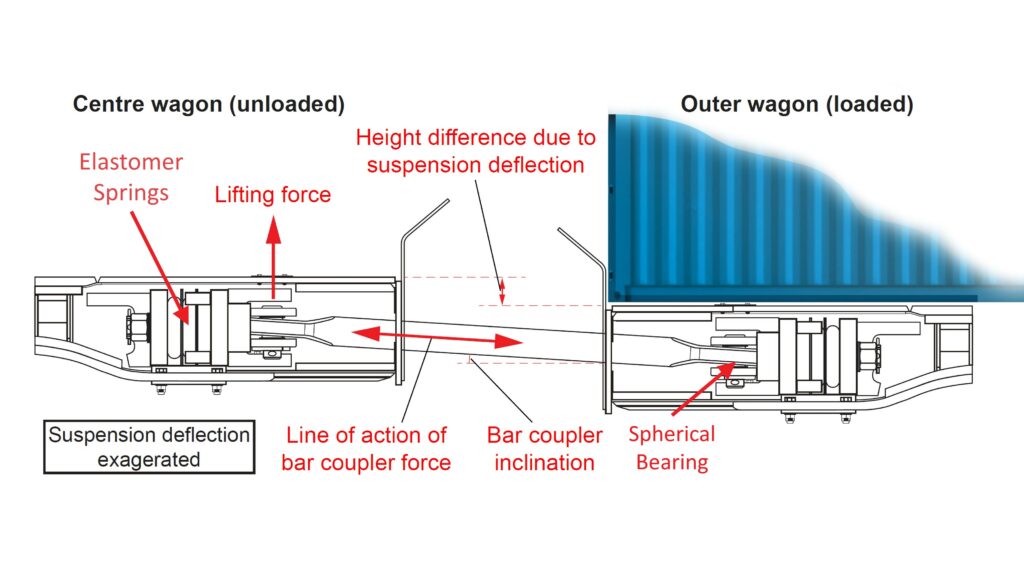
Figure 2 shows a photo of an Ecofret 2 wagon consist with a side elevation. Outer wagons are nearly a metre longer than centre wagons to accommodate the buffers and screw coupler which are mounted above the wagon spine, which is lower in order to accommodate today’s taller containers. The intermediate bar couplers are mounted below the wagon deck/spine, consisting of a metal bar secured in a housing in the wagon headstock. Elastomer elements are included in-line to absorb energy in response to tension or compression loads. The illustration, right, shows the configuration of wagons 11, 12, and 13. The suspension of the loaded wagons will be compressed more than those on the unloaded wagon, resulting in the bar coupler being at a slight angle to the horizontal as shown in figure 3.
Investigation
As already stated, the first wagon to derail of the 33-wagon train was wagon 12, the unloaded middle wagon of a three wagon permanently coupled FWA-Ecofret 2 type. All other wagons on the train were loaded with at least one container. The wagons either side in the triple wagon set – wagons 11 and 13 – were each loaded with one container weighing 18.9 tonnes and 20 tonnes, respectively.
When investigating a derailment, it is usual to look for either an obvious cause such as a broken rail, or the point at which the wheels flanges first ride up onto the top of the rail and the distance the flanges ran along the rail before dropping into the cess. In this case, the RAIB reported that there was evidence that both wheelsets on the leading bogie of wagon 12 had suddenly lifted, moved to the left, and had remained ‘airborne’ as the train travelled about 1.5 metres. In lay terms, the bogie had ‘jumped off the track’. There were no top of rail witness marks. The other wagons which derailed were as a consequence of this first one.
Similar derailments
Similar Ecofret 1 wagons had derailed in 2015 at the Port of Felixstowe and at Peterborough. In both cases the wagons were around the centre of the train and the middle wagon was unloaded. The rail industry investigation concluded that the cause was high compressive forces on the bar couplers. This led to a recommendation that longer bar couplers be provided.
A train jumping off the track was identified in the RAIB investigation into the collision between an Inter-City Express Train (IET) and a High Speed Train in November 2019 on the approach to Neville Hill depot. In this investigation, the trailing bogies of the second, third, and fourth cars of the IET derailed. In simple terms, the compressive shock force of the collision taken though the centre bar couplings caused the trailing ends of those cars to lift and move sideways taking the bogies with them. Observers made comparisons with pole vaulting in athletics.
Following a collision of a freight train with farm machinery at Kisby in August 2021, the middle wagon of an unloaded Ecofret 2 set derailed.
While the RAIB was investigating this collision, the London Gateway derailment took place and, as the wagon derailment aspect of the Kisby collision appeared similar to those described above, it was investigated as part of the London Gateway work. Its investigation sought to estimate the compressive load on the couplers on this train at the point of derailment together with modelling the magnitude of the load required to produce this effect.
Results
The RAIB identified the immediate cause, together with causal and underlying factors.
The immediate cause was a longitudinal compressive force generated within the train during braking sufficient to cause the wheels on the leading bogie of wagon 12 to suddenly lift over the top of the rail and run derailed. Evidence pointed to the left hand wheels of both wheelsets on the leading bogie of wagon 12 simultaneously contacting and then lifting over the left hand rail. This was similar to the previous incidents at Felixstowe, Peterborough, and Kisby with Ecofret wagons in the middle of the train. The report explained this mechanism (see also figure 4).
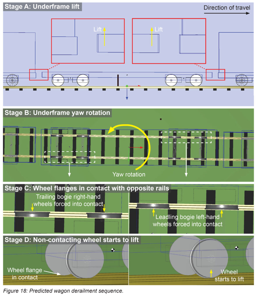
Stage A: the underframe of wagon 12 started to lift.
Stage B: the underframe of wagon 12 then started to rotate when viewed from above (yaw rotation).
Stage C: as the compressive force was increased further, the wheel flanges on the leading bogie started to contact one of the rails, while on the trailing bogie the wheel flanges started to contact the opposite rail.
Stage D: wheels opposite to the wheel flanges in contact then started to unload, eventually lifting off the rail.
Stage E (not illustrated): finally, one of the bogies rose clear of the rails, derailing fully as a result.
A maximum compressive force of 451kN was identified from extensive modelling and this force would have been rapidly generated just before wagon 12 reached the derailment site. The RAIB devoted considerable space to the modelling which went far beyond what has previously been carried out for evaluating longitudinal forces and discussed the sensitivity of the modelling to the number of data uncertainties and assumptions involved. RAIB was mindful that the largest force calculated (451 kN) was less than the baseline wagon derailment simulations predicted as being needed for full derailment (650 kN).
RAIB concluded that the gap between the predictions probably arose from data uncertainties and assumptions that were needed to allow the simulation work to proceed. It added that the inconsistency could be explained and, given the significance of the other supporting evidence and the lack of evidence supporting any alternative derailment cause, the conclusions drawn could be relied upon.
There were two causal factors. Firstly, wagon 12 was susceptible to derailment under longitudinal compressive force and its condition, and the loading of the Ecofret 2 triple-wagon of which it was a part, increased this risk.
This causal factor arose due to a combination of the following:
- The design process for Ecofret 2 wagons did not fully recognise the need for there to be a change in design from the Ecofret 1 wagon to improve behaviour under longitudinal compressive forces. The report describes options that had been considered and rejected when mitigations for the derailments on Ecofret 1 wagons and the design and approval process.
- The RAIB suggested that it was possible that bogie degradation and wear led to the wheel flanges being more prone to being forced into contact with the rail under longitudinal compressive force. This related to the mechanism that had been fitted to the primary suspension to control lateral motion of wheelsets relative to the bogie frame.
- Having wagon 12 unloaded between loaded wagons 11 and 13 made the wheels of wagon 12 more prone to lifting under longitudinal compressive force (see figure 3).
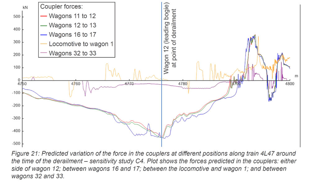
- Secondly, the longitudinal compressive forces generated during braking and which acted on wagon 12 were large, significant, and sudden. Investigative work showed that compressive forces were high towards the middle of the train but low at the ends. The output of modelling for a distance of 25 metres either side of the derailment point provided evidence that the longitudinal compressive force generated during braking was likely to be higher than at other locations along the length (see figure 5).
- The high compressive force was caused by a double brake application resulting in a sudden and large longitudinal compressive force being generated that acted on wagon 12. This coincided with wagon 12 approaching the derailment point.
Much more detail is available in RAIB’s report.
The RAIB identified two underlying factors:
- Derailment risks associated with the longitudinal dynamic behaviour of long freight trains are not widely understood within the rail industry and there are limited supporting processes, tools, and knowledge available to assess and manage them.
- VTG Rail adopted design management arrangements that possibly limited its ability to understand the dynamic behaviour of the triple-wagon as a complete vehicle system and did not result in it identifying critical subsystem performance requirements that were associated with the behaviour of the train as a whole.
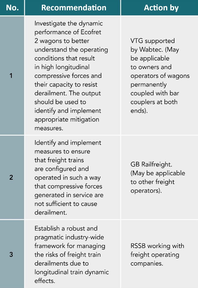
Recommendations
Three recommendations were made, summarised to the left.
As with so many RAIB investigations, this investigation highlighted that it is not a single factor that leads to an accident but weaknesses in a number of risk controls coincide to cause the defined hazard, in this case, the derailment. The knowledge gained during the investigation will be invaluable for the freight industry and timely completion of the actions should ensure that there is more knowledge available to designers, manufacturers, and operators to ensure safety by design of freight trains and their operation.
Freight train traction and braking
Unlike most modern passenger trains with distributed power, almost all freight trains have a locomotive hauling the train. On a passenger train the couplings hold the train together, and generally see only the tension load of one or two trailer coaches (except in recovery situations). In braking, the brakes apply simultaneously on each coach, so the couplings see comparatively little compressive load.
For freight trains, the loco to first wagon coupling has to cope with the tension load of all the wagons in the train. This load decreases along the train. There is another factor though. The couplings are generally not entirely ‘tight’. There might be some slack and/or movement to be taken up in springs, elastomer shock absorbers in the couplings, or small gaps between the buffers. If the driver were to apply power suddenly, as though a metro train was being driven, there would be considerable tension snatch in the couplings – a pulse force – that on very long trains could snap a coupling.
The opposite can happen in braking: compressive forces in couplings. Generally, all freight wagons are braked, the brakes are controlled by reducing the compressed air pressure in a pipe along the train known as the brake pipe. Air is exhausted at the loco end and propagation of this ‘signal’ along the train takes a few seconds.
Thus, the back of the train might still be unbraked/coasting whilst the front of the train is braking leading to significant compressive forces through the couplers.
If the emergency brake is suddenly applied or, worse, there’s a collision, a very significant compressive force pulse is seen through the couplers. Where vehicles are coupled with bar couplers with no side buffers, compressive forces can lead to significant lateral (jack-knife) motion restrained only by rails and wheel flanges (see figure 6). In some circumstances the movement might have a vertical component (figure 3) as was the case here.
Illustrations sourced from RAIB report.