The completion of the £30 million restoration of North Wales’ iconic Barmouth Viaduct was celebrated on 8 December, marking the end of a four-year programme that has fully restored the 156-year-old, grade II* listed structure, and maintained its historic appearance, including a complete replacement of the metallic superstructure.
Barmouth Viaduct is a single-track viaduct across the estuary of the Afon Mawddach near Barmouth. It was constructed by the Aberystwyth and Welsh Coast Railway between 1864 and 1867. It is 770 metres long and carries the Cambrian Line between Morfa Mawddach and Barmouth stations. Its 113 spans of 5.8 to 6.2 metres make it the longest timber viaduct in Wales and one of the oldest in regular use in Britain.
When built, the bridge included a lift span to pass tall ships. In 1906, three fixed and swinging metallic spans were installed, carried on cast iron cylinders. As well as the railway, the spans support a path, used by pedestrians and cyclists as part of National Cycle Route 8. To the people of Barmouth and Meirionnydd it is a vital link between communities, taking children to school, and people to work, shopping, and the doctors. The now completed restoration works will ensure that this link continues for generations to come.
The project was split across several years to reduce the impact on rail services, the community, and local economy. In Rail Engineer 192 (Sept-Oct 2021) the repairs to the timber viaduct were described, and these works were delivered between 2020 into 2022 during two long blockades. 2023 saw the complete replacement of the metallic spans, undertaken during a 13-week blockade of the coastal route north of Machynlleth. With the use of a jack-up barge impractical here, the logistics of installing the new 160-tonne spans were extremely complex, requiring a multitude of temporary works and innovative construction techniques to slide the new bridge into place, and at the same time demolish the old structure.
Network Rail’s route director for Wales and Borders Nick Millington said: “It’s a fantastic achievement for the teams who have worked tirelessly in all weathers to complete the job, which will enable the viaduct to safely carry rail services for many years to come.”
The contract for the project was awarded to Alun Griffiths Ltd, which is locally based and is proud to be delivering a project which brings economic, social, and transport benefits to the area.
Network Rail’s Gareth Yates and Steve Richardson of Alun Griffiths explained the logic, design, and delivery of this epic project to Rail Engineer.
Design
Network Rail worked closely with Transport for Wales, Cadw, Gwynedd County Council, and other stakeholders over several years to develop and agree the scope of this project.
The requirement was to replace and restore the metallic elements of this listed structure on a like-for-like basis, maintaining the historic aesthetic of the 156-year-old bridge. A further, and significant, challenge was to devise an installation methodology in conjunction with Alun Griffith’s team. The structural design was undertaken by Tony Gee and Partners, supported by Cass Hayward. The approved design visually replicates the original bridges, although reflecting current design codes.
The long-disused swing span of Br 41 was not required to be movable but, with the agreement of Cadw and Gwynedd County Council, it retains the existing slew path and other equipment on the centre pier to reflect its previous form. Dummy rivet heads are included on top flanges of the hogback trusses to reflect the old structure’s appearance. The two northern approach spans of Br 42 were designed to match the original Warren trusses.
The hogback trusses and overhead bracings for the fixed and two halves of the swing span of Br 41 are of conventional design. However, for installation much temporary steelwork was added to these. A runway beam, for gantries, was added above each truss. Substantial end connections were added between the ends of the two pairs of trusses. These would enable the two spans to be connected end-to-end, forming a single rigid structure that would allow complex temporary loading situations required during installation.
Fabrication and delivery
The contract for the new steelwork was to have been undertaken by Cleveland Bridge, which had also built the existing 1906 structure. However, following its closure during 2021 the works were instead delivered by Doncaster-based Carver Engineering Services.
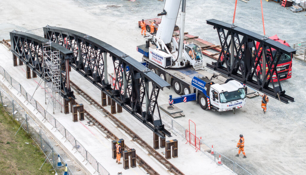
The new trusses were trial assembled and painted at its works, but split into thirds for transportation, carried vertically on road vehicles. These were delivered in July to the compound at Morfa, south of the river, for assembly and trial moves, before rail transport across the estuary. Steelwork for the short land end spans were delivered to a smaller compound on Marine Parade in Barmouth and transported to site by pontoon.
Advance works
All of the construction works were to be delivered over tidal water and, unlike the previous timber works, had no low-tide mudflat access to the site. Works access was from the old bridge itself or from floating platforms. Attridge Scaffolding erected hanging scaffolding around each pier to give access for repair and painting works above low tide level. Scaffolding was also erected to the trusses at the future demolition cut lines and was clad to ensure no pollution of the river below.
The new steelwork would arrive by rail, but the existing structure was to be removed from site by pontoons on the river. Graveyard Beach, beside Barmouth’s harbour, was the unloading point for the dismantled bridge and a safe access to this was created from Marine Parade.
ScaffFloat assembled four 12-metre x 8-metre 63-tonne capacity pontoons and, to push/tow these, two ScaffFloat Workboats with 1.5-tonne bollard pull capacity. Lifts were carried out at slack tide, but anchors were installed either side of the bridge. Deck winches attached to these, and to the bridge piers, were used to hold the pontoons in position to a tolerance of 100mm.
To avoid any conflict with normal river and harbour traffic, the installation of temporary moorings and the intensive movement of boats and pontoons between bridge and beach was agreed with the Barmouth Harbourmaster and covered by a Marine Licence from Cyfoeth Naturiol Cymru (Natural Resources Wales).
On the bridge itself, the existing overhead bracing was raised to allow the new bridge beams on rail trailers to pass through.
Community engagement
The importance of the bridge to the life of the local community meant that this project had already attracted a huge amount of interest during the previous years’ works. Local social media was very active and supportive of this final element of the project. In advance of the works, a drop-in event was held on Barmouth Quay and was well attended. The regional significance of the works was reflected by the coverage it received on regional and national news programmes. Local students enthusiastically followed the project and were visited by project engineers to explain the works and to try the ‘Griffith’s Bridge to schools’ bridge building challenge.
Steelwork erection and test move
As the truss steelwork was delivered it was erected on 12 short trestles on a concrete pad at the Morfa compound, adjacent to the Cambrian line. Onto these were placed extensive temporary steelwork, for the overhead runway beam (seen blue in images) and for temporary end connections. At this stage, and for the move, the new trusses were set about 1.8 metres closer than their final position. This would enable them to pass along and through the existing bridge.
The operation to transfer the assembled spans across the timber viaduct, and to position these onto the substructures, was going be both unique and extremely complex. To verify the transportation methodology a practice move was carried out on a purpose-built 92.5-metre track between the trestles and steelwork. This used longitudinal timbers and rails retained from the timber works in 2021. The first span was successfully moved along the test track onto a second set of trestles leaving the first set available to erect the second span. Additionally, the planned horizontal sliding of the beams was trialled here together with the cantilevering of the swing span, described below. This ensured that all key blockade activities had been successfully trialled, with lessons learnt incorporated into the methodology and temporary works design.
Moving the trusses
Once the blockade began on 2 September, Ekki timber mats and packings were installed on each cess of the Cambrian line. The rail trailers were positioned between these, and a Mabey bridge truss installed along them. This acted as support to the trusses during the delivery, served as bracing between the two during the demolition and slide out operations, and provided access across the bridge during the demolition and reconstruction works.
A 400-tonne crane then lifted each 63-tonne hogback truss onto the timbers and, after fine adjustments, attached to the Mabey truss for stability. The second truss was then placed and the overhead bracings between the runway beams installed, forming a rigid structure ready for transportation.
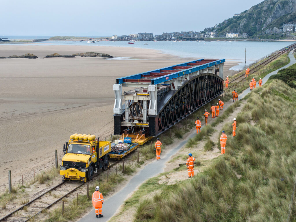
Once assembled, the 200-tonnes of the spans and temporary works were jacked off the packings from their train of six rail trailers and set at 722mm above rail level to clear the viaduct handrailing. The train was propelled by a Unimog road/rail tractor, which had accessed the track at Fairbourne.
The compound test had proved that the transport methodology was sound, but it was recognised that stopping the spans in a millimetre perfect position would not be possible using the Unimog alone. A tow bar was therefore constructed that included a Macalloy hollow ram jack that could be used to pull/push the train for the last 100mm.
The steelwork was supported on the trailers by 20 jacks that were monitored throughout the less-than walking pace move across the timber viaduct. In practice, the West side remained static and adjustments were made to the East side to reflect any minor cross level variations of the track. The cross level was monitored by a fixed spirit level viewed by Mabey’s jack operator using a GoPro camera. A maximum safe wind speed of 12m/s (26mph) had been set, but the weather was calm during the two moves.
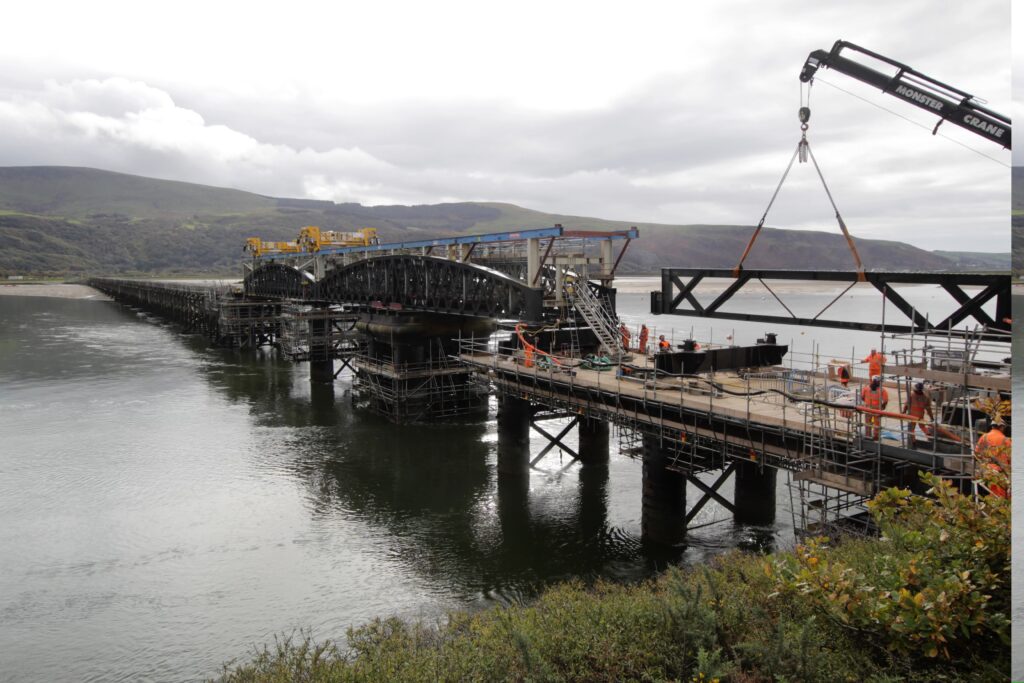
The two new structures now stood within the old bridge in their correct locations above Piers 2, 3, 4, and 5 (piers numbered from northern abutment). The supporting trailers were locked in position and the Unimog returned to the compound. At this stage the site was very complex, the Mabey truss on the trailers was surrounded by the new bridge trusses which were in turn surrounded by the old structure.
Installation and demolition
Prior to their removal from the trailers, for stability, the new and old bridges were connected together using timber blocks and ratchet straps. The new steelwork was then supported on temporary steel stools on the pier support beams, the trailers withdrawn, and the trusses lowered from their travelling height of 722mm above rail to 325mm, and re-strapped to the old bridge. Once both spans were lowered, the temporary end connections were made above Pier 4, forming a continuous rigid structure.
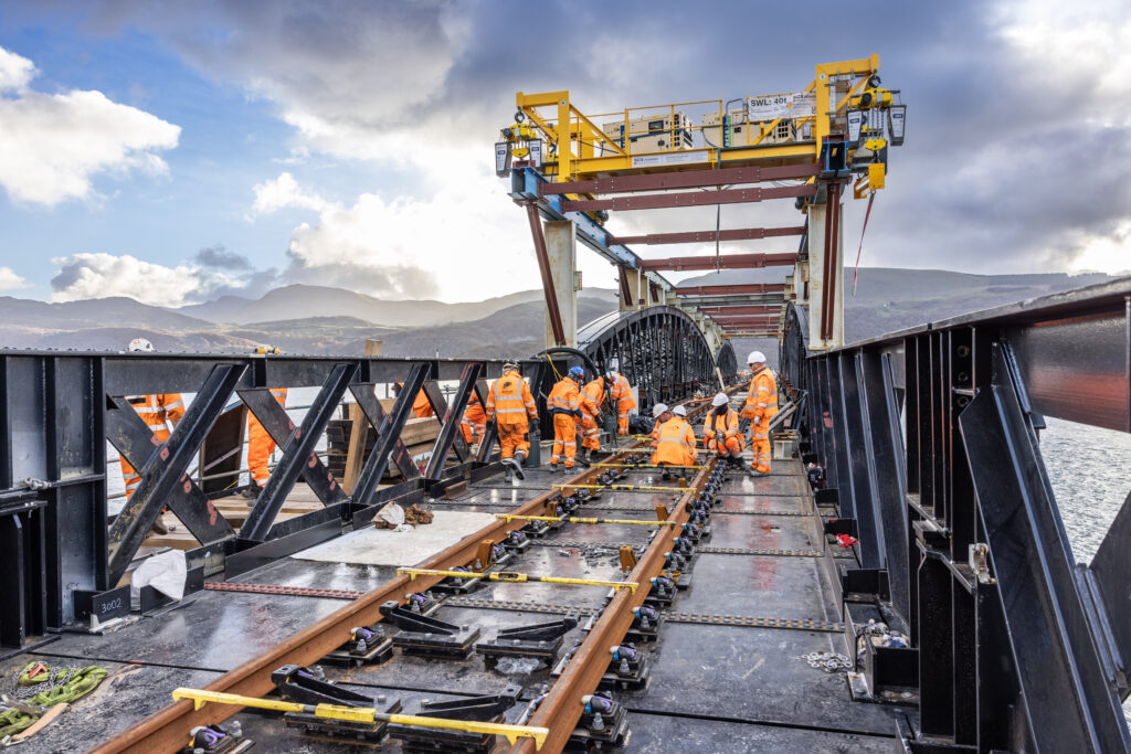
Most of the lifting and handling of the demolition works and installation of new crossbeams and deck works was carried out using travelling gantries that gripped beneath and above the top flange of the runway beams above the new trusses with 4 x 10-tonne hoists. These were named Henry and Benjamin, for Henry Conybeare and Benjamin Piercy who jointly designed the original bridge. The installation of these was carried out from the north end by a SK200 Monster road/rail crane standing on Span 42.
During the demolition of the existing structure, its weight was suspended from the new steelwork. The underslung cross girders beneath the runway beams (seen grey on images) had hinged extension pieces that were swung out into position above the top boom of the existing trusses. From these, Macalloy suspension bars were attached to the old metalwork to support this while the vertical cuts were carried out by the Pennys Group demolition team.
Then, using the gantries, the sections of around 23 tonnes each were attached with straps and hooks. These were quick to release and had no chains to rub or snag. Once the hoists had taken the load, the suspension bars were released, and the bridge sections lowered onto one of the pontoons, which were then taken by a workboat to Graveyard Beach. Pontoon movements were restricted to slack water and so the demolition programme reflected the varying tide times. At the beach the metalwork was cut up using hydraulic shears, avoiding the potential environmental contamination of flame cutting.
The demolition of the two approach spans of Br 42 was more straightforward and were dismantled sequentially from Pier 2 back to the abutment using the SK200 crane.
Following the removal of the ring beam, an H frame was installed, bearing on the four cylinders of Pier 3 forming the crossbeam support to the centre of the new ‘swing’ span trusses. Once this had been installed then the new trusses were jacked down to 125mm above final level.
In order to replace the crossbeams on Pier 2, the whole new truss structure was lifted by jacks at Pier 3 to provide airspace at Pier 2, with the whole of the temporarily joined trusses now cantilevering out beyond Pier 3.
With all new crossbeams now in place on each pier, the trusses were jacked down onto slide paths on each beam. Now at last the trusses could be jacked outwards by 963mm into their final positions and secured. The travelling hoist structures and overhead bracings both included telescopic members that allowed them to adjust to the increased width between trusses. The complex works to get the new trusses into place were now complete.
Works to the main spans had the use of the travelling gantries for most operations, however for the works to the approach spans, particularly for Span 1 of Br 42, cranage was severely limited. The limited standage at the abutment meant that the SK200 crane, the largest that could be used, would not be adequate for all lifts. Temporary gallows brackets were installed to each side of Pier 1. The existing crossbeam was then horizontally jacked across onto these. This small but significant reduction in lift radius brought it within the capacity of the crane. Once removed, the reverse operation was used to land and place the new cross beam.
The weight of the new Warren trusses for Br 42 Span 1 were in excess of the crane’s capacity and so, at this stage, six bracings were omitted and replaced with two light sections. Once placed, the bracings were installed followed by crossbeams and decking. Span 2 being much closer to the crane, was installed with trusses complete. Slave rails were then installed on both spans for future crane and trolley access.
The permanent 56kg/metre FB running rails and BH guardrails were delivered by rail, running along the temporary track. KGJ Price Rail, using the SK200 Monster crane, removed the slave rails and placed new 60 foot lengths into combined baseplates directly fastened to the deck plates.
With the structure substantially complete, the internal temporary Mabey bridge truss was dismantled from the north end, using trailers and RRV working from the slave rails. Finally, after the PW works, the temporary runway beams, hoists, and bracings were dismantled and the permanent overhead bracings installed by the RRV running on the permanent rails. With localised painting works, the new structure was then complete.
Return to rail traffic
Before the bridge was returned to traffic on 2 December, Network Rail and Colas Rail replaced around 300 metres of track from the viaduct towards Barmouth.
A formal opening on 8 December was attended by Network Rail, Wales Office minister Fay Jones, and representatives of the community, rail industry, and local council. A plaque marking this project milestone was unveiled.
Future rail travellers, pedestrians, and cyclists will see and appreciate the smart new structure that has replaced the rather tired original. What they will not see is the huge amount of thought, ingenuity, and planning that went into delivering this project. It is one that our industry can be rightly proud of and a credit to the many contractors and individuals involved in its success.
Image credits: Mulhollandmedia / Barbara Fuller