

Getting a reliable 25kV power supply is important in the thrust to obtain more railway electrification commitment from the government. All too often, reports emerge of train services being disrupted because of problems with the power supply.
Over the years, the design of overhead catenary supports and conductors has been standardised and enhanced. Also, by having the 50kV auto transformer option, this gives the capability of delivering more power whilst negating the need to have booster transformers and return conductors. One might comment that the structures and gantries have become excessively sturdy judging by the GW main line project but, overall, the emphasis has been to reduce the cost of electrification.
But what about the power from the electricity supplier? Is this robust and reliable – and what happens if power to a substation fails? A talk given recently by Tobias Thurnherrs from Hitachi Energy, at an event organised by the IET Midlands Power Group, looked at one way of improving the quality and resilience of power feeding the railway.
Conventional power feeding
The electricity supplier has a multitude and mixture of different power lines ranging from 275kV and 132kV high voltage pylon lines down to 33kV and 11kV for local distribution. These operate in three-phase, which is an efficient and balanced way of distribution. For the conventional feed, only the higher 275kV or 132kV are used to supply the catenary, this being achieved from where these power lines run close to the railway.
A transformer connects only one phase of the grid to the 25kV overhead line at what is known as a substation (sometimes called a feeder station). Ideally, these substations are around 25 miles apart. This is not an ideal arrangement as it creates an imbalance between the three phases. However, for transmission lines of 132kV and above, this is not generally an issue as the load on each phase is much greater than the power taken by a railway substation feeding the 25kV OLE.
Midway between substations is a track sectioning cabin (TSC) which separates the feed sections from the adjacent substations. Since the two power sources may not be in phase or indeed will have slightly different voltages, the TSCs control what is known as a neutral section. This is a short length of catenary that is unpowered and prevents the two feeds from combining and causing disruption to the grid supply. Normally, trains coast through these neutral sections at speed but it is not unknown for a train with only a single pantograph to become stranded in the neutral section if it is moving very slowly or has stopped because of an unrelated problem. The train thus loses all power, and a recovery train or locomotive has to be sent out to pull or push the stranded train a short way to regain a power supply.
Should a substation fail, then it is disconnected from the 25kv catenaries and the TSC connects both sides of the neutral section to allow power to be extended a further 25 miles to the next TSC point. In such circumstances, the voltage drop on the catenary can be significant (it may get as low as 17kV) thus impacting on the power needs of trains.
None of this is liked by the grid authorities. The transformer being a passive component represents an inductive impedance and creates both active and reactive power related to the railway load. The feeding grid sees an undesirable power factor and an unbalanced load.
Static Frequency Convertors
To overcome some of these difficulties, a lot of research and effort has been put in to designing an intermediate device between the transformer and the catenary feed. This is known as a Static Frequency Convertor (SFC). It is something of a misnomer as whilst it can convert the 50Hz frequency into something different, its main role is to control the precise voltage, phase angle, and frequency of the output.
If this can be achieved, then the power output from adjacent substations can be made identical and thus the neutral section can be dispensed with if the sections either side are fed from SFCs . In the process, the control of the active power flow is better controlled and the reactive power reduced. That, in short, is what an SFC attempts to achieve.
SFCs work by taking a three-phase balanced load from a high-voltage transmission line, converting it to DC and then to a single phase 25kV OLE supply. As a result, their use does not affect the balance between the transmission line’s three phases. Hence, they can be fed from a local distribution network’s 33kV supply.
The benefits of feeding the 25kV OLE from a 33 kV supply are considerable as this significantly reduces the cost of substation connections and offers greater flexibility in the location of substations.
Other benefits are that, in the longer term, SFCs could replace existing substations so that a single section of the line need not be dependent on only a single feed. With multiple feeds from different substations, more power can be delivered to trains and thus fewer substations are required. At peak demand, a train will take power from more than one substation and thus the capacity to provide the necessary power is enhanced. The catenary voltage will be better stabilised as it is no longer vulnerable to a single three-phase supply from the grid being below specification. Further, the capture of regenerative braking is enhanced. Should a short circuit occur on the catenary system, the control of the short circuit current can become more manageable.
It is unlikely that these other benefits will immediately impact on existing electrified lines as this would require the replacement of existing substations, perhaps during renewals or power supply upgrades. For new electrification schemes, SFCs should represent a considerable cost saving.
The trial site
A number of countries are already using SFCs but for Britain, a trial site was needed. By chance, a new supply was needed for the Doncaster depot, where one of the Hitachi Azuma trains are stabled for maintenance and cleaning. This is known as Potteric Carr, just south of the station, and the opportunity was taken to use this as a substation to power the 25kV wires from Doncaster to Bawtry, some eight miles to the south. Should there be a fault in adjacent feeder stations, the power can be extended to Retford in the south and to York in the north.
A contract was let with Hitachi Energy to supply the SFC as part of a turnkey package that included site preparation, groundworks, foundations, transformers, harmonic filters, heat exchangers, a cable connection to the OLE, and commissioning. The substation would be integrated to the national SCADA system to enable control from the Electrical Control Room (ECR). The local 33kV from the national grid had to be upgraded and equipped with gas insulated three-phase switch gear. The SFC is designed to integrate with other SFCs north and south when those substations are converted.
From the Network Rail position, the SFC rating is required to deliver peak power of 46.5MW for two seconds, continuous power of 30.5MW, a unity power factor over the voltage range of 25kV to 27.5kV. It has to withstand a temperature range of -25ºC to +40ºC during normal operation, be capable of operating with any harmonics generated by the traction units, and must not interfere with track circuits or other elements of the signalling. In addition, the SFC must comply with IEC / EC and UK power standards, mainly BS EN 50121-1,2,5 plus Network Rail Group Standards NR/SP/SIG/50004 and RT/E/C 50008. The SFC uses integrated gate commutator thyristor (IGCT) technology with high-quality semi-conductors to guarantee a long life and low losses.
Also, the SFC has to operate with adjacent substations still using the traditional transformer fed section and to other SFCs that might be supplied by a different manufacturer. This will ensure degrees of freedom to share power and including synchronous coupling with transformer fed sections. It also means that a data transmission link will need to connect and control the synchronisation, but this will be part of the SCADA system.
Installation and testing
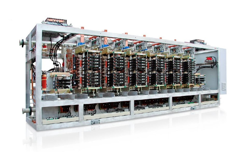
The SFC is installed within a containerised building where the incoming grid supply is connected with a three-level neutral point clamped converter and a 100Hz filter to filter out any pulsating load from the single phase of the grid. The SFC contains a phase measurement unit (PMU) that measures the amplitude and phase angle of the output voltage, which is given a time stamp that can be transmitted to adjacent substations and the ECR. This enables effective load sharing and allows to offset the angle measurement to prevent unwanted power flow through the catenary.
Short circuit faults do happen occasionally which can reflect back into the grid and cause a voltage dip. When using an SFC, this limits the effect a short circuit can have compared to a transformer fed arrangement. Protection relays are provided to monitor impedance and so detect and isolate a fault. Sufficient current must be provided to the SFC during a fault condition. This has been tested at Potteric Carr and a stable output current is provided during the fault. A smooth ramp up of voltage occurs once the fault is cleared.
SFCs do generate noise and at Potteric Carr, a house and a nature reserve are close by. The walls of the building are equipped for fire protection that provides the necessary insulation that ensures noise emission levels are within the required limits.
Testing of the SFC has been extensive, especially the software testing which used a digital real time simulator, followed by on site testing, mostly done at night to prove suitability for both old and new type trains.
In conclusion, whilst SFCs themselves are more costly than the transformer fed system they offer significant reduction in supply connection costs. They also offer the benefits in terms of a simpler, more resilient, and evenly balanced power supply with the prospect of needing fewer substations in the future, making this a worthwhile investment. Time will tell if the necessary investment will be forthcoming.