

Wheelsets come in all types and sizes − large, small, solid; with tyres and without; powered, trailer; inside bearings, outside bearings; and sometimes as individual wheels. Wheels are the heaviest and probably the most expensive consumable parts on trains, and they are safety critical parts; although there are many wheelsets on a train, each is a single point failure risk, and wheels/axles rarely fail safe. Degradation can happen through wear, but serious flat spots or cracks leading to fractures can, and do, lead to derailment.
The railway industry rightly focusses on continuously improving wheelset safety and management. Its work is led by the RSSB sponsored Wheelset Management Group (see panel). For many years the Institution of Mechanical Engineers (IMechE) has held wheelset seminars to share developments and issues. The most recent event was held at the Institution’s Westminster HQ in April 2022. This article reports on a selection of the presentations.
The keynote speaker, Bridget Eickhoff, principal infrastructure engineer at RSSB, has had a long career in vehicle dynamics. She highlighted the challenges still facing wheelsets some 200 years after the principle of coned wheels fixed to an axle was first proposed by George Stephenson. As well as the single point failure risk mentioned above, they operate in an extremely harsh environment (accelerations >80 g are often measured) and they represent a large proportion of fleet maintenance cost. Each area of the industry (tram/light rail, passenger, freight, high speed, etc.) has its own issues and challenges. Finally, as heavy consumable items there is an environmental challenge with the embedded carbon in the steel.
Wheelsets support the vehicle mass, steer the vehicle along the track, roll with minimum resistance, transmit all braking and traction forces, and support brake discs and transmission components without wearing out rails unnecessarily. They do all this through a contact patch that is approximately the area of a five pence coin. Bridget said that the contact pressures are extremely high and much higher than any other rolling contact application.
Remote monitoring
Using the principle of what gets measured can be managed, there were two presentations about wheelset measurement. Dr Martin Rosenberger, head of vehicle dynamics, acoustics and analytics at Siemens Mobility, Austria, talked about digitisation in wheelset maintenance. He said that his objective was to move from corrective and preventive maintenance towards condition-based and predictive maintenance operations, with the aim of delivering better availability, reduced life cycle cost, improved safety, longer life span of components, and reduced environmental impact.
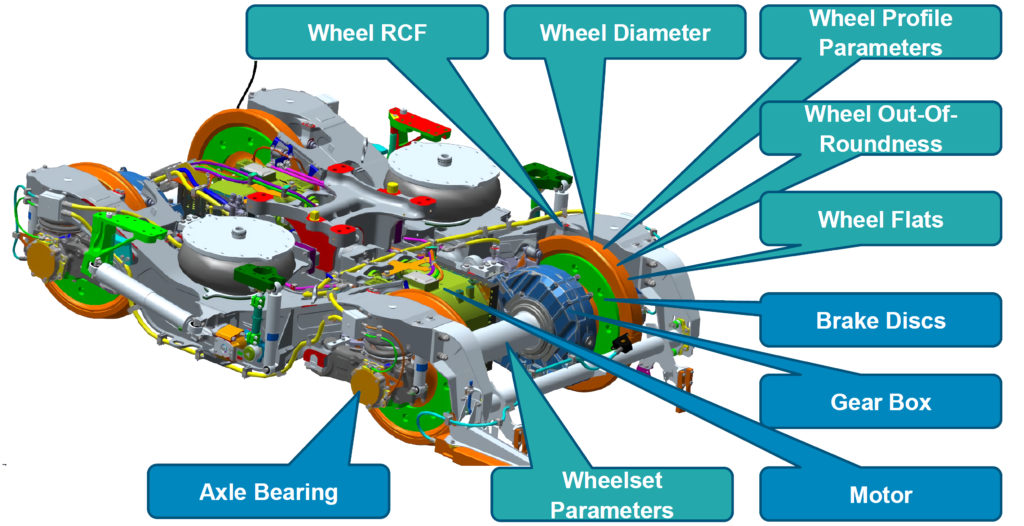
Wheelset maintenance tasks include inspection, reprofiling, and exchange. The adjacent diagram highlights the wheelset parameters (in turquoise) and other influencing components (in blue). The objective of inspection (data acquisition) is to indicate the health status of the various components, and their remaining useful life both of which are used to plan workshop activity. The digitisation process is aimed at automating all these tasks. Martin highlighted three levels: Acquisition level – including wayside vehicle measurement systems, on board diagnostics and wheel lathe measurements; Execution level including – a computerised maintenance management system and management dashboards; and finally Strategic level – digital twin; and the core element for a digital system, an Internet of Things platform connecting all different levels and tools.
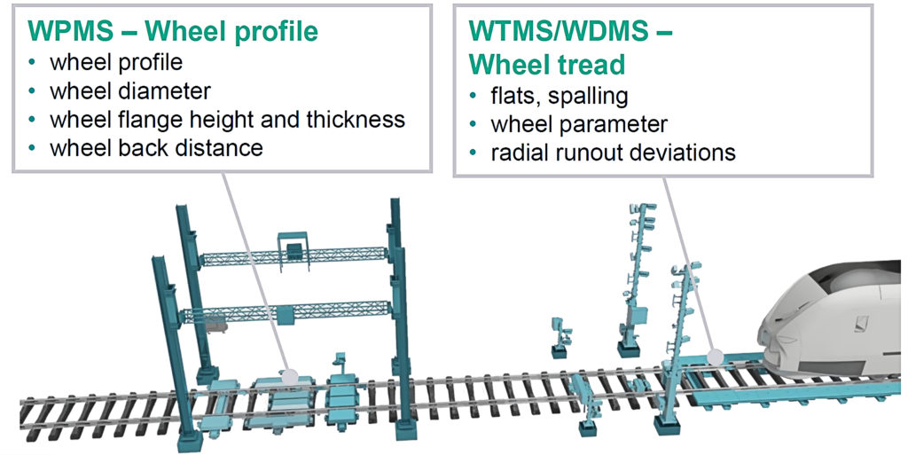
Wayside systems can measure most wheelset parameters: profile, diameter, flange height and thickness, back-to-back, and tread defects, including flats, spalling, radial runout. These devices are often located on the entry/exit of depots.
On board systems typically use accelerometers and speed sensors to identify wheel flats, out of roundness, wheel diameter, wheel profile parameters, and axle, gearbox, and motor bearing issues. If these sensors are connected to the train’s computer systems with Wi-Fi/4G communications data and/or alerts may be sent continuously.
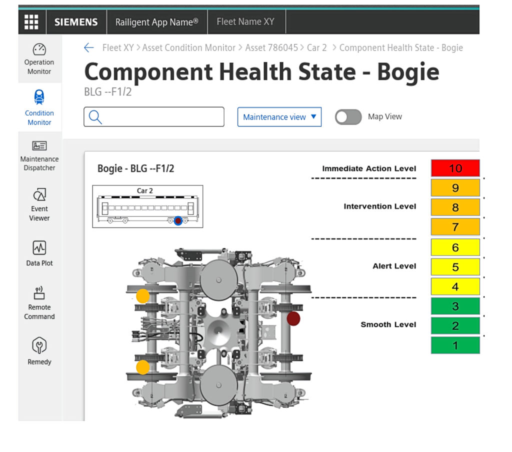
For the Internet of Things data platform, Martin stressed the importance of an “open ecosystem” to allow data from a variety of sources and in a variety of formats to be integrated to enable “advanced analytics and decision making”. He said that this information would be input into the maintenance logistics planning and management system with the automatic generation of work orders. Martin also demonstrated sample health status screens from Siemens Railigent® software. His final slide highlighted this system already in use in Siemens depots, for the 115 class 700 Thameslink trains.
Wheelset load monitoring
A new decision tool for condition-based maintenance of wheelsets was demonstrated by Steven Cervello, innovation and design manager for Lucchini RS, Italy. Axle non-destructive testing is often mandated at fixed intervals of either time or distance, but the actual loads experienced by wheelsets vary by route. A straight, flat route will tend to have lower loads than routes with significant curves and/or gradients. Steven introduced Smartset®, an instrumented wheelset that collects loads which are used to calculate crack propagation rates and hence estimate appropriate NDT intervals.
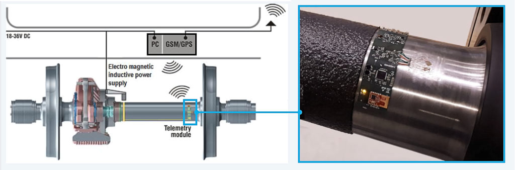
Smartset comprises three main components: strain gauges to measure bending and torsion stress in the axle; a telemetry module to send the signals by Wi-Fi to a carbody mounted data unit; and an electro-magnetic inductive power supply to provide energy to the electronics (for freight vehicles with no built in power supply, an axle end generator may be fitted). The data allows engineers to carry out stress frequency analysis.
Steven demonstrated that on a mountainous route there were significantly more stress cycles in the medium-high range than for the same train running on a flat coastal route, influencing the optimal inspection interval. He also showed that the information combined with GPS signals allows engineers to identify locations where loads were higher than usual (often associated with switches and crossings) and to monitor them to detect potential track deterioration over time. Once the impact on the axles is understood, engineers are able to identify the appropriate NDT intervals for that fleet, something that can be kept under review as service patterns change over time.
Steven said that the system should be fitted to both trailer and motor wheelsets. In response to questions, he said that generally only one of each is required to be fitted on a given fleet/route as the objective is to characterise the route, rather than continuously monitor every wheelset.
Wheelsets for Very Light Rail (VLR)
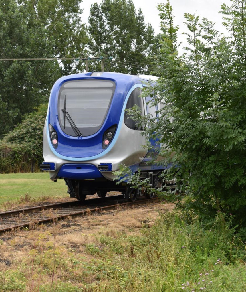
Adrian Howson, chief technical officer at Transport Design International (TDI), described the Revolution VLR vehicle which was covered in issue 193 (November/December 2021), before focussing on the bogie and wheelset design.
The aim of the RVLR design was to be light weight so that the cost of the track and other infrastructure, as well as the propulsion energy, might be reduced. When the prototype vehicle was commissioned, Adrian’s team thought “where can we get two bogies for our prototype?” Having considered bogies from scrap Manchester trams which were “too challenging to clean up and adapt”, TDI’s research identified that freight bogies were often made in small numbers and could be motorised. The DB Axiom (part of Wabtec) LN25 bogie was selected. Adrian said: “In hindsight we chose well for our principal application – a rugged proven bogie, perfect for sub-optimal track on restored lines – and we are now getting enquiries for the powered bogie for many other applications such as electric freight”.
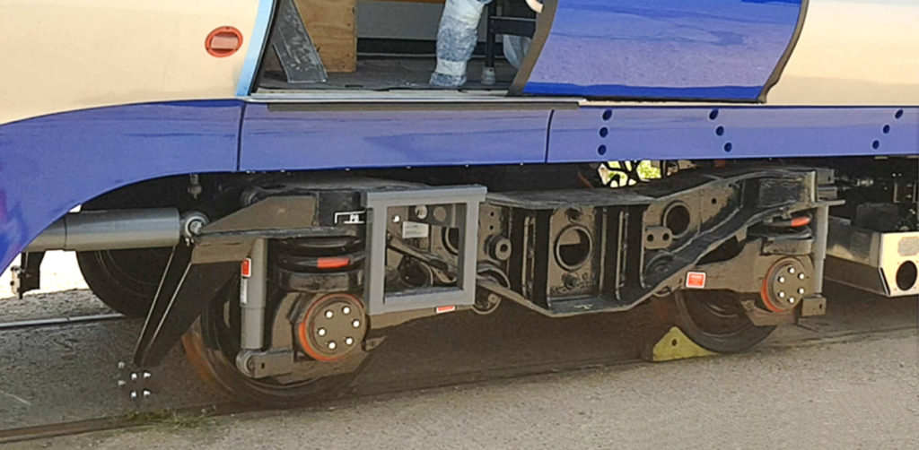
To use the Wabtec LN25 bogie, TDI needed to make a number of changes which included reducing the wheel size to reduce the height, developing a drive train, and having the masses and fixings approved by Wabtec.
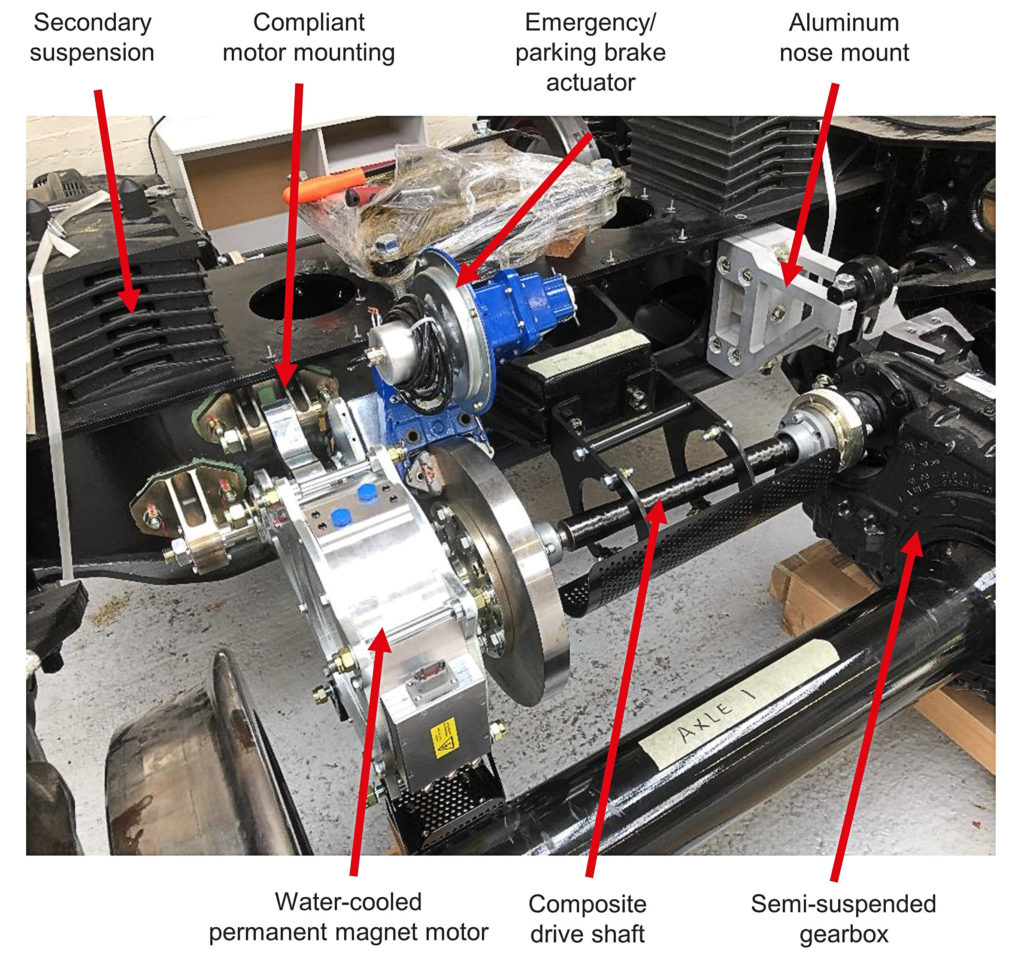
Wabtec was also asked to configure the suspension for optimum comfort. To reduce the bogie mass, TDI removed the standard freight brakes, installed hollow axles, used smaller 720mm diameter wheels, fitted lightweight axial-flux automotive motors on a suspension mount, and added carbon fibre drive shafts and aluminium brackets. The unsprung mass of the freight wheelset (1086kg) was reduced to 967kg in this version, including the gearbox. Overall, the fully motorised bogie still weighs less than the original freight bogie by some 140kg.
No brakes? Don’t worry!
There are no brakes on the wheelsets, as the RVLR uses its traction motors to brake the vehicle to stationary, and the brake disc adjacent to the motor is a parking (and emergency) brake, spring applied and electrically released. This approach saves considerably on weight and maintenance. Adrian added that magnetic track brakes could be added for routes which operate by line of sight.
Adrian addressed the track-wear impact of smaller wheels compared to a class 153 vehicle. This is approximately the same capacity as the RVLR, weighs 55% more, and has 840mm diameter wheels. RVLR has a lower wheel load to diameter ratio and the peak stress on the wheel is some 27% lower than that of the class 153. Adrian said that RVLR has delivered “best in class” low weight, meaning low wheel loads for reduced wear – despite the smaller diameter – and low track cost, ideal for restoration and line reopening.
Steering bogies – extending wheel life
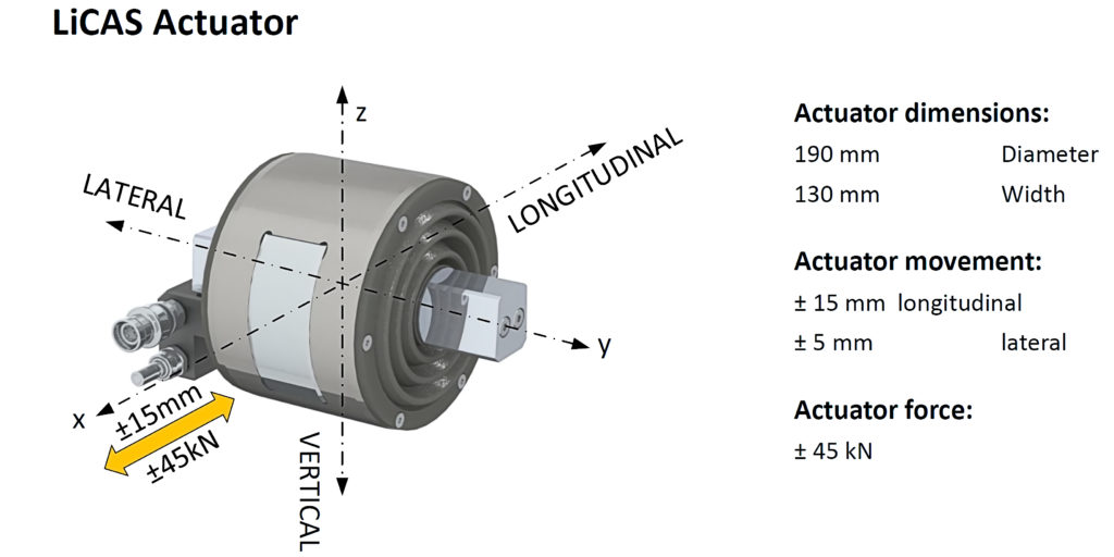
Liebherr Controlled Active (LiCAS), a smart axle steering solution for existing rail bogies was presented by Rob Wheeler, director sales and customer Service UK & Scandinavia, and Ivo Kovacic, systems engineer for hydraulic applications, both from Liebherr-Transportation Systems. The principle of this system is that diagonally opposite wheel bearings are moved towards or away from the bogie transom under hydraulic power in response to a carbody/bogie rotation sensor. The principal aim was to develop an actuator that could be retrofitted to bogies with radial arm primary suspension in place of the radial arm bush.
The actuator delivers longitudinal movement of +/-15 mm and lateral movement of +/- 5 mm. The maximum longitudinal force is +/- 45 kN. Simulations have demonstrated improvements in each of the following parameters: angle of attack, T-gamma, track shifting force, rolling resistance, the lateral force of the wheel flange on the rail (Y), and the ratio of this to the vertical wheel load (Q) known as Y/Q. The steering was able to work down to a radius of 200 metres and a 30% to 50% reduction in wheel maintenance cost was forecast.
The actuators were fitted to a BT10 bogie on a withdrawn mk3 carriage and tests were performed on the Weardale Railway in County Durham. Eighty-one test runs with different control settings were carried out including 10 combinations of control settings with five steering factors and five failure modes: passive mode, curve detection, actuator position detection, leakage, and fault control. The failure modes were tested to ensure there was no risk of derailment even with adverse actuator positions. The track included: high track and curvature irregularities, variation of rail head geometry, low adhesion (high humidity, rainfall), and cant excess (low speed).
The tests were carried out successfully. LiCAS worked as expected. A significant reduction of angle of attack and T-gamma was demonstrated. The tests also validated the simulations and a significant reduction of track access charges was forecast. Finally, the LiCAS system was able to be classified as fail-safe for the BT10 bogie.
Sustainability
A new topic at the IMechE Wheelset seminar was a presentation about the sustainability of wheelset manufacture. There is a great deal of embedded carbon in wheelsets and a modern train is likely to use at least four sets of wheels and several brake discs during its life. The presentation ‘Energy Impact of Wheelset Component Manufacture’ had been prepared by Moira Trimarco, CSR Manager, Lucchini RS and was delivered by Steven Cervello.
Lucchini is a global company with over 2000 employees, an annual turnover of over €400 million, and nearly 800 clients in 45 countries. Railway production includes circa 250,000 wheels, 40,000 axles, and 12,000 completed wheelsets per annum.
Steel is eminently recyclable, but unlike with inkjet printer cartridges, it is impractical to include a pre-paid envelope to return scrap wheels! Although some scrap wheels do get recycled by Lucchini, the overwhelming majority of raw material used is other scrap steel. Steven emphasised The Lucchini way: Reduce, Re-use, Recycle. Reduce raw material, energy and waste; Re-use scrap and water; and Recycle machining scrap, scrap wheels, and axles.
Steel production is energy intensive and Lucchini generates 0.76 tonnes of CO2 eq per tonne of steel produced. That said, this value is much better than is usual in the steel sector (up to 1.9-2.0 tonnes of CO2 eq per tonne of steel). Most importantly, Lucchini invested in electric arc furnaces which already have the potential to use electricity from renewable sources (currently 40%). This has allowed Lucchini to reduce its emissions by over 3,800 tonnes of CO2 eq emissions during the past 2 years.
Lucchini are focussing on reducing the energy needed and hence the carbon emissions at every other stage of the production process. Eighty-eight percent of the energy was used in steel making (59%) and machining (29%). Machining is also, of course, powered by electricity with the opportunity to use renewable sources.
All this is part of Lucchini’s GREEN ID; a methodology to report the greenhouse gas emissions associated with the product’s lifecycle (cradle to grave – or cradle to cradle to emphasis recycling) in accordance with ISO 14067 Carbon footprint of products – Requirements and guidelines for quantification. Lucchini divided the entire process into three main steps: Upstream (raw material, packaging, transport); Core (manufacturing, maintenance, waste, transport to customer); and Downstream (Periodic maintenance, product end of life). Steven added that the customer can receive a kind of identity card, where the total carbon footprint associated to the entire life of the products is expressed in kilograms CO2 eq.
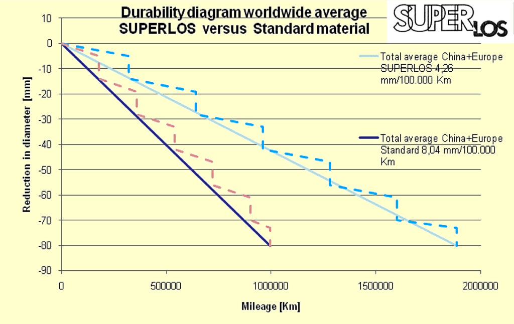
The final big opportunity is in the hands of users. Steven showed a graph showing the average life of a wheel made from Lucchini’s SuperLos steel. This showed an approximately 90 % improvement compared with standard steel, which might roughly halve the number of wheels required during a train’s life.
Axle non-destructive examination
The final presentation of the day, ‘Towards the Obsolescence of In-Service Ultrasonic Axle Testing’, was given by Roger Deuce, principal specialist & technical manager, wheelsets, at Alstom.
Examining axles using ultrasonic non-destructive examination (NDE), looking for defects that could lead to a crack or a fracture, is part of the in-service maintenance regime for most axles in the UK. Given the improvements in the steel making processes, product quality assessment measures, and the use of modern-day robust design philosophies, confirmed indications from these in-service axle inspections have become rare. Comments from the floor suggested that the main reason for scrapping axles was actually as a result of defects in wheelsets caused by fitting or removing wheels.
Roger recollected the origins of many of today’s NDE requirements citing a Railway Inspectorate report into a derailment caused by a broken axle on a 1949 Shenfield Type electric multiple unit on 13 December 1963. The report recommended that “no axle should be tested less frequently than once in every 18 months”. A later accident caused by a broken axle on a freight wagon on 8 March 1996 at Rickerscote recommended, amongst other things: improved axle surface preparation; better protective coatings and coating maintenance; a review of NDE frequencies and methods; consideration of theoretical predictions of crack propagation; consideration of the use of MPI in addition to ultrasonic inspection; and a review of overseas experience with NDE techniques and axle coatings.
These two reports, together with the learning from two other significant events in Germany (2002 and 2008) and one in Italy (2009), have significantly influenced many of today’s axle NDE standards. The current EN15313:2016 and RIS-2766-RST (2017) standards clearly require the definition of an NDE regime (e.g., MPI or ultrasonic inspection). This must include, where appropriate, the required activities at overhaul as well as in-service between two overhauls. As a minimum, the regime must be verified to ensure that, if a defect in the axle is just below the detectable size, then it will not grow to failure before the subsequent inspection.
Roger described the process by which the technical expert might assess the maintenance regime required, including load/stress levels in the axle, the ability of the inspection method to detect cracks, the allowable size of crack to ensure no failure before the next inspection and the risk of false alarms. Justifying extensions of time are somewhat easier with hollow axles as the entire outer surface can be examined using ultrasonic probes running along the entire inner surface of the axle bore, therefore enabling a higher detection sensitivity due to the reduced scanning distance.
It is more challenging to justify extensions if solid axles are retained, but a similar assessment process can be used. However, there are now modern computer-aided ultrasonic inspection processes available using phased array scanning which can provide new opportunities for solid axles.
Other techniques available include redesigning the axle to reduce working stresses, as well as potential material techniques such as induction hardening, cold rolling, and, as Roger said, “avoiding exotic material grades”.
Roger concluded by showing a photograph of a series of axles intended for Alstom FLEXX Eco bogies destined for use under Alstom’s Aventra EMUs by the use of hollow axles and by designing the axle with reduced working stresses Alstom has been successful in achieving a key industry goal of no longer requiring in-service ultrasonic inspection.
Once again, this seminar demonstrated that there is a lot of innovation under way to improve safety, and performance whilst reducing cost.
Thanks to John Reddyhoff, who led the organising committee and to the presenters for their help in preparing this article. All photographs and illustrations courtesy of the presenters/their companies.
Wheelset Management Group (WMG)
WMG is a subgroup to the Vehicle / Track System Interface Committee (V/T SIC). Its purpose is to provide an industry forum for wheelset management issues including safety performance, standards (new, current and legacy for design, manufacture and maintenance etc.), the supply chain, maintenance best practice, and applicable research. The scope includes the following wheelset components:
- Axle.
- Monobloc wheel.
- Wheel centre, tyre, and retaining ring.
- Axle bearings.
- Brake disc.
- Transmission or final drive, including suspension tubes.
- Axle box / radial arm.