

When Brunel planned his railway route between Exeter and Newton Abbot, he probably knew he was challenging himself to a significant task by choosing to follow the coast closely along the Exe estuary, the open seashore through Dawlish to Teignmouth, and then the Teign estuary. Along the open seashore section of the route the challenge was to create a ledge for the railway to run along and then to protect that infrastructure from both below and from above.
Protection from potential damage below in the shape of wave action and storms took the form of substantial masonry walls and beach groynes. Protection from potential damage from above in the shape of landslips and cliff falls from the fairly weak New Red Sandstone took the form of judging the appropriate grading of the excavated cliff faces or, perhaps the easier option, the provision of five tunnels. It is widely known that over the years the sea walls have suffered several failures, often leading to closure of the line. It is probably less well known that the cliffs have also caused problems for safe operation of the railway, particularly over more recent years.
Site of new rockfall shelter
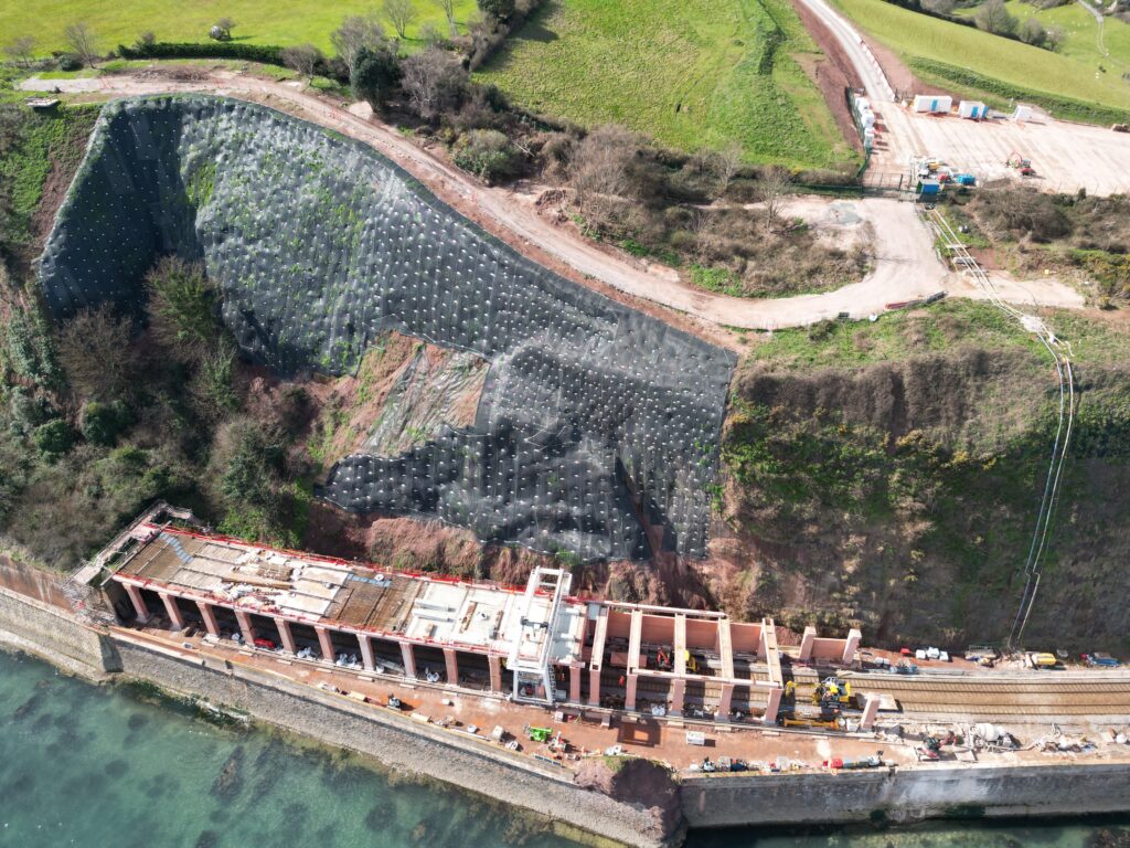
To say that the site of the rockfall shelter is inaccessible would be a serious understatement. It is situated above a rocky shoreline at the foot of 60-metre-high cliffs and in a short section of open line between two tunnels. The nearest significant road access is the busy Dawlish to Teignmouth main road, 600 metres from the clifftops. The nearest rail access points suitable for loading rail vehicles are at Newton Abbot, 6.5 miles away or at Dawlish Warren, 2.5 miles away. There is a restricted access point suitable only for personnel, small plant, and light materials at Smugglers Cove at the west end of Parsons Tunnel.
Evolution of the scheme
The works form Phase 3 of the South West Resilience Programme, which has already seen the major works carried out as Phases 1 and 2 for the new sea walls and station enhancement work around Dawlish.
Because of the varying nature of the cliffs in terms of exact rock formation, slope, vegetation cover and water features, the route adjacent to the cliffs has been subdivided and designated into Cliff Behavioural Units (CBUs). Phase 3 addresses the problems presented by CBU 17. Phase 4 will cover CBUs 18-26 and will involve slope stabilisation and enhanced netting installation.
The cliffs at the eastern end of Parsons Tunnel have been previously subject to much protection, with rock bolted netting to minimise the risk of falls onto the operational railway. But these measures, evaluated by the Resilience Study, were now deemed inadequate. This led to the decision to provide a much more robust type of defence in the form of a rockfall shelter. The length was originally going to be around 200 metres, but a value engineering study eventually reduced this to only 109 metres.
Design details
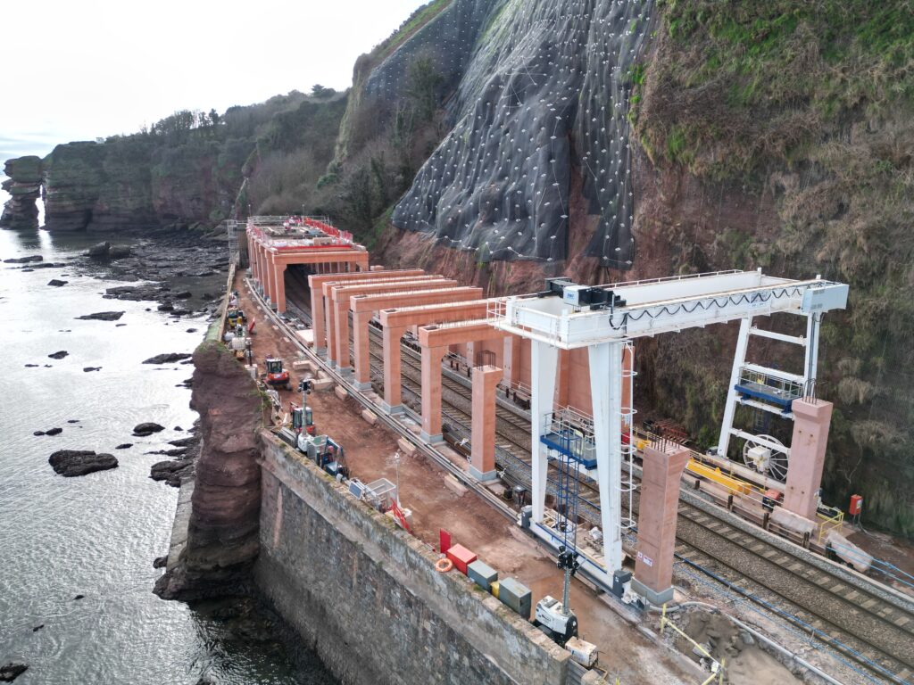
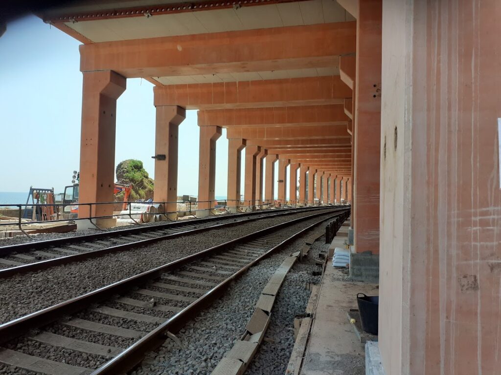
The design of the rockfall shelter consists of 19 reinforced concrete portal frames, each of two columns and a cross member. The roof is a reinforced concrete slab, and the cliff side of the structure is of wall panels against which backfill between the structure and the cliffs could be placed. Interestingly, the seaward side of the structure is left open to preserve the sea views for those extra few seconds of a journey.
The main contractor for the design and build works is Morgan Sindall, which has established a very well set up site office, messing, and safety facilities in a compound just off the main road. A subsidiary messing area at the end of a haul road, right at the top of the cliffs above the site of the rockfall shelter, has also been created to provide staff welfare facilities a little closer to the site and also to stable such plant as mobile concrete pumps and generators. Even from that area there is still a 17-flight scaffolding stairway to gain access to track level. This route crosses the coastal path and padlocked gates either side of the path are necessary.
Prefabricated units
The concrete portal frames were prefabricated by Cornish Concrete and delivered by road to Hackney Sidings at Newton Abbot. The concrete has been subtly coloured a very light shade of red to blend aesthetically with the natural geology. This was achieved by experimenting with varying quantities of a synthetic iron oxide pigment, supplied by Proctor Johnson, added to the concrete mix until the desired effect was achieved.
These trials were done as small ‘Lego’ blocks. Once the desired colouration had been approved at the concrete works by Morgan Sindall, the appropriate block could be viewed and compared with the geological setting on site by Network Rail, Morgan Sindall, and the local planning authority. Production of the correct colouration for the actual columns and beams was achieved by scaling up from the pigment mix trials.
Fabrication of the columns and beams was quite complex. Cast into the foot of each column is a 400kg shear key and six Peikko Bolda column shoes, each weighing around 100kg. The columns were cast in a horizontal position, but nevertheless the weight of the steel ‘attachments’ meant that timber shuttering at the base would be totally inadequate to maintain the correct geometry and positioning of these critical fixing components. Even with 25mm thick steel plating for this area of the formwork, additional complex support arrangements were needed during casting.
As for the cross beams, U-shaped in cross-section, and with narrow floor and wall widths, and congested reinforcement, great care was needed to ensure correct concrete compaction. Both columns and cross beams are designed with exposed reinforcement where the two elements are joined in situ. To check the exact positioning of the reinforcement and to avoid a clash between each of the major structural elements, Daniel Burrows, design and technical director for Cornish Concrete, explained that it was essential for the fabricator to go beyond the structural design as produced by Arup and to actually model the spatial interaction of the two elements.
This was done using a Building Information Modelling (BIM) software package from Tekla Structures.Each column weighs in at 17.5 tonnes and each cross beam at 22 tonnes. They were brought by road from Truro to Hackney sidings at Newton Abbot to await transport to site by rail. In addition to these 38 column units and 19 cross beams, the other prefabricated components for the structure are 34 edge beams, 76 wall panel units, and 94 parapet units.
Programme and construction aspects
The works commenced in Autumn 2021 and are scheduled to be complete by Christmas 2023. Major possessions were used between Christmas 2021 and February 2022 to bring lineside plant and materials to site and to construct lineside gantry rails for the overhead crane. The first major activity was the installation of bored piles, being the foundations for the columns. The piles are 450mm diameter installed with a Klemm 702 piling rig. There was a requirement for nine-metre-long steel casings to form the upper section of each pile. It was not permitted to have these made up of shorter sections, site welded, and so manipulation and placement of the casings was a significant task.
The piling work was carried out in special 6.5-hour weeknight possessions, which necessitated the temporary suspension of the overnight Penzance-London sleeper services in both directions for a period. Rory Shavrin, project director for Morgan Sindall, told Rail Engineer that very good understanding and assistance with amending train operations was had from Great Western Trains, Cross Country Trains, and Railfreight.
Ben Shearing, senior project engineer civils for Network Rail, explained that following pile installation, the construction of pile caps and pad foundations to receive the precast column units was not a straightforward process, because of the limited working space. Further temporary sheet piled walls propped off the permanent piles that were needed to support the track, enabling construction of the permanent pile caps and column foundations. This was largely because of the proximity of the running lines to this work.
The prefabricated concrete elements were brought by rail from Hackney Sidings using a Unimog towing up to 10 flatbed trailers. Columns could fit along a single trailer, but the cross beams had to span two trailers. The wall units were stacked three-high on the trailers. With the Unimog being limited to 5mph, considerable cumulative possession time was needed to get all the units to site.
Unloading and positioning of the concrete units was effected with a twin girder Goliath 20 tonne gantry crane. This was a bespoke version of the standard crane with the span increased by Morgan Sindall specifically for the site. A clever feature of the design of the column units is that they were supplied with a single lifting point, just close to the centre of gravity, calculated to be in the correct position such that when lifted from the trailer by the gantry crane, each unit would swing to hang exactly vertical, making final positioning and placement onto the foundation that much easier.
There is such limited space at the site that there was no possibility of storing any of the major components at the lineside. Therefore, it was very important to have the facility to lift the units directly from the rail wagons to their installed position. The cross beams had two lifting points and were simply lifted into place with a spreader beam. Longitudinal deck units forming permanent shuttering were then installed spanning between the main cross beams and finally work proceeded on the reinforced concrete decking, creating a deck of overall depth of 500 millimetres. This work was able to safely continue whilst rail traffic was running.
There are some final stages of the work still to be carried out. Firstly, the backfilling of the space between the wall panels and the cliff face, which has been covered with a membrane. This will be achieved by pumping in an estimated 5,000 cubic metres of very weak concrete. Then a layer of sand, one metre deep, will be placed all over the rockfall shelter deck, which will have a parapet on the seaward side. The sand layer is to spread punching loads from falling boulders and to prevent any such falls bouncing off the shelter. Finally, the remaining area of cliff face where the shelter is not being provided, is being subjected to rock scaling, soil nailing and netting installation. CAN Geotechnical Ltd is providing the labour and plant for this work, with materials supplied by Morgan Sindall.
Pumped concrete for all the works is delivered by vertical 5-inch and 4-inch pipelines from the compound at the clifftop. These pipelines incorporate double bends to prevent separation of the mix through intense gravitational effects. There is also a static pump at the base of the cliffs for onward delivery. Refuelling of all lineside plant is by road/rail delivery of fuel cubes.
History repeating
What was not revealed at the start of this article is that this current rockfall shelter work is an extension of a very similar project which was completed a century ago. The original Parsons Tunnel was 374 yards in length. In 1920 it was found necessary to extend the tunnel eastwards by 147 yards with the provision of a rockfall shelter for the same reasons as in the present day. A five-ring brick arch was built on a travelling falsework. The arch was supported from two brick walls and the falsework was moved on guide rails outside the operational lines.
Like the current project, the space between the new shelter and the cliff face was backfilled with concrete and the roof was grassed over. Will it be another 100 years before the ‘tunnel’ has to be extended further eastwards? Hopefully, the value engineering which reduced the proposed length of the new rockfall shelter will be vindicated, and such further extension may never be needed.
The works are being funded effectively under the Rail Network Enhancements Pipeline (RNEP) and the cost of Phase 3 is estimated at £50 million.
Image credit: Network Rail / Mark Phillips