

Bob Hazell
Plain line railway track construction is designed to resist the operational forces associated with passing trains and the forces and impact associated with the prevailing weather conditions. However, as global temperatures increase, more of the current track construction types get closer to the Critical Rail Temperatures (CRTs). This then starts to impact on the track’s stability in very hot conditions.
Steel rails expand as they get hotter and contract as they cool down. The coefficient of expansion (how much it expands as it gets hotter) of normal grade carbon steel, commonly used in the manufacture of rails, is 0.0000115 per °C. Manganese steel rail, a harder wearing steel used in limited amounts has a coefficient of expansion of 0.000018 per °C, which is some 56% greater than that of normal grade steel.
Air temperatures in Britain this summer broke all-time records reaching 40°C in Lincolnshire on 19 July. Rail temperatures on hot days with no wind or cloud cover can reach 20°C or more above the air temperature. This resulted in rail temperatures in the high 50s °C.
Typical rail temperatures in the UK have normally varied from -15°C, some winters lower, to 55°C. This resulted in a typical overall temperature variation of 70°C. This variation, and the resultant rail expansion and contraction must be safely accommodated in the track design.
Based upon the above temperature ranges, in theory, the West Coast Main line between London Euston and Glasgow Central is 540 metres longer on a hot summer day than it is on a cold winter’s night. Of course, the distance between London and Glasgow doesn’t vary, so how is the expansion and contraction accommodated on this, and all other routes, and what does the increasing risk of higher rail temperatures mean for the track engineer?
Jointed track
The management of thermal expansion and contraction of rails was historically dealt with by creating a joint with a gap between each rail. The normal length of rails in jointed track on the UK network was and still is 60ft (18.288 metres), although longer lengths, up to 120ft and shorter rails exist. The joints, at 60ft intervals, results in the classic clickety clack noise as trains passed over them.
Jointed rails are joined by fishplates, of which there have been various designs. The fishplates and fishbolts in jointed track were designed to allow contraction of the rails in cold weather and expansion in hot weather, without the rails and track becoming distorted and buckling. Typical examples are shown in the photo below. The diagram below shows the typical dimensions of the fishbolt holes in the rail and fishplate, as well as the fishbolt diameter.
Based upon a 70°C rail temperature range, a 60ft rail will expand and contract by 15mm. Correctly manufactured rail joints can allow approximately 11mm expansion, therefore, at the hottest temperatures the rail in jointed track is in compression, and at the coldest temperatures the rail and joints go into tension. The colder temperatures induce forces on the bolts, fishplates as well as on the fishbolt holes in the rails.
Jointed track, and the joints themselves are labour intensive to maintain, particularly in terms of preparation for hot and cold weather. The rail joints require annual lubrication, which involves removal of the fishplates, inspection of the rail ends for any signs of visible cracking, lubricating the underside of the railhead and upper part of the rail foot (the fishing surfaces) that contact the fishplate, and then replacing the fishplates and bolts, tightening them up to the correct torque.
Ultrasonic testing avoids the need to remove the fishplates to detect cracking of the ends and fishbolt holes in the rails. Developments in lubricants by companies such as Interflon, mean that fishplate lubrication can be carried out without the removal of the fishplates. Whilst these developments reduce some of the maintenance requirements, some rails in jointed track can creep along, generally in the direction of traffic.
This creep causes bunching of the rails and the closing up of the expansion gaps. The gaps require monitoring and measuring and, if too many consecutive rail expansion gaps are closed up in the cooler weather, the rails and rail gaps need to be adjusted, regulating them, so that the correct expansion gaps are available before the onset of hot weather.
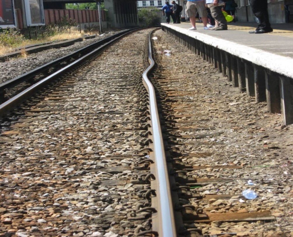
Track buckle in jointed track
Failure to carry these maintenance tasks out can result in the jointed track buckling. An example of a track buckle in jointed track is shown in images on this page.
As global temperatures rise, the focus on the correct maintenance of jointed track becomes even more critical if track buckles of this track form are to be avoided. Even minor deficiencies, including that of the ballast profile, can result in a reduction in the critical rail temperature which, in turn, results in the risk speed restrictions being applied to limit the track forces applied.
Track ballast
Both jointed and continuously welded track rely on track ballast for the stability of ballasted track. The angular nature and interlocking of the ballast provide frictional resistance to both the underside (soffit) and sides of the sleepers. The frictional resistance increases as the ballast and sleepers consolidate themselves due to the repetitive loading from rail traffic. The increased consolidation results in an increase of the calculated CRT. If track is disturbed, typically by tamping or activities that disturbs the ballast, the frictional resistance is reduced.
This frictional reduction results in a reduction in the CRT. It is essential, therefore, that track is not disturbed in, or just before the onset of hot weather. If ballast must be disturbed, the calculated CRT must be adjusted (lowered) and any necessary mitigation, such as speed restrictions to reduce the impact forces on the track, applied until sufficient traffic has been carried to fully consolidate the track and ballast.
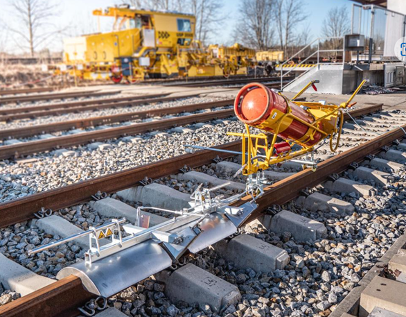
On-track machines with dynamic track stabilisation (DTS) can be used to accelerate the consolidation of the track and ballast and increase the CRT. DTS machines can be used to reduce the risk of speed restrictions in hot weather but were originally introduced to consolidate newly laid track to allow it to be opened to traffic at higher speeds, up to 125mph.
Long welded rail
With the requirement to reduce maintenance, improve ride quality, and increase speeds, developments were made with trials of long welded rail. Initially, bullhead rails were used. These were welded into 300ft lengths with machined tight joint fishplates joining the long welded rail. London Passenger Transport Board started installing long welded rail in 1939. By 1948 some 60 miles of track had been laid on the London Transport network.
In a 1948 paper to the Institution of Civil Engineers, the author Cedric Dunton tentatively concluded the maximum rail length of 1470 feet (448 metres) with a breathing gap between rails of five to nine inches (127-229mm) could be achieved in long welded rail. The breathing gap was achieved with what were then called expansion joints.
Long welded rail reduced the number of joints the maintenance teams had to maintain and helped to improve ride quality, but it still had a significant number of joints and required maintenance input to prepare for the various seasons, especially summer.
Continuously welded rail
The next step was to develop continuously welded rail (CWR). Trials on the mainline railway were undertaken on the Southern Region and in France, but it was not until 1953 that early CWR was trialled and installed on other Regions of British Railways.
In those days the track consisted of softwood sleepers with cast baseplates or chairs, with early pre-stressed concrete sleepers installed on the later trial sites including a site at Llanwern.
The Llanwern site consisted of two sections of CWR track, each half a mile in length. The 300ft rails were further welded on site using the thermic welding process into the full half mile length.
Expansion or adjustment switches were installed at each end of the CWR to allow for expansion and contraction of the end sections of the CWR. These expansion switches also isolated the stresses in the CWR from the adjoining jointed track.
In the early days of CWR, before the development of hydraulic stressors, the rail was heated and expanded to the correct stress-free temperature using rail warmers before being clipped down to the sleepers. Rail warmers are still used, mainly in complex areas where it is not possible to use hydraulic stressing equipment or where a sufficient stress anchor cannot be achieved, typically in and around switch and crossing layouts.
Today, CWR is stressed to 27°C when it is installed. This is the stress-free temperature (SFT). It is, therefore, in tension at temperatures below this and in compression at temperatures above 27°C.
CWR is delivered to site in lengths of 216 metres on special CWR trains. These lengths of rail are then welded on site making them a continuous string of rails with no expansion joints (some insulated joints may be welded into the string for track circuit signalling purposes). The rail is clipped to sleepers, which tend to be concrete, although timber, steel and plastic sleepers are used in Britain. The heavier concrete sleepers offer good resistance to buckling.
When installed, the rail, before being clipped down to the sleepers, is physically stretched, usually using hydraulic tensors. The extension required is calculated using the difference between 27°C and the actual rail temperature, and the length of free unclipped rail and coefficient of expansion of the steel used to manufacture the rail. To limit the effects of friction on the length of free rail during the stressing operation the rail is placed up upon rollers.
There is no maximum limit to the length of rail that can be welded together but there are limits on the length of rail that can be stressed in one go, mainly due to limitations of the stressing equipment and the greater risk of an uneven pull due to snagging of the rail over longer distances, along with the risk on curves that the rail will attempt to straighten itself whilst being stretched. To prevent the rail from pulling in, side rollers, to guide the rail, are installed on curves during stressing. The maximum length of free rail when stressing is 900 metres.
When the correct expansion of the rail has been achieved for the rail temperature, the rollers are removed, the rail is clipped down to the sleepers and welded up with the adjacent rail to form a continuous length.
Records are kept of the stress in the rail. The stress achieved during the stressing operation is known as the stress free temperature (SFT). This is normally 27°C but can vary between 21°C and 30°C.
Other, less common methods of stressing the CWR include heating the rail and natural stressing in warm weather. Heating or thermal stressing of rails is achieved by using a heat source that is moved along an unclipped rail until the required rail temperature and expansion is achieved. When the correct temperature is achieved the section of rail at the correct temperature is lowered from rollers and clipped to the sleepers. The operation must be achieved swiftly before the rail starts to cool below the required SFT limit.
Natural stressing can be used, where the sun, or ambient temperature, warms the rail to achieve the required SFT. In this case the unclipped rail is still placed upon rollers but the rail expands naturally without using tensors or heaters. The rail must be clipped down and welded before it becomes too hot in which case the rail becomes overstressed.
Adjustment switches are now generally only installed at interfaces with jointed track and some older switch and crossings layouts that were not designed for the high stresses encountered in CWR.
Rail expansion joints are installed where there is a requirement to isolate the track stresses and longitudinal forces from that of large structures that the track passes over, typically around large span underbridges.
Special precautions
Special precautions are required when replacing rails in CWR. The rail stresses need to be maintained or restored to 27°C. The process is strictly controlled, and records taken of the changes in rail and the stress achieved. If there is insufficient possession time to maintain the correct stress in the rail, and the replacement rail is installed with an SFT significantly below 27°C, plans must be put in place to restress the rail before the onset of hot weather. This is often why, along with sites of any recently disturbed track and any known weaknesses, speed restrictions are applied in hot weather. Speed restrictions reduce the impact forces upon the rail and track which reduces the risk of instability. As global temperatures increase and rails suffer higher temperatures, the risk of speed restrictions increases.
The high temperatures of summer 2022 have seen an increasing number of hot-weather-related speed restrictions applied. In some cases, the sites become so numerous that it is not possible to sign all of the locations on site, so blanket speed restrictions over large areas are applied. The first of these was applied in the summer of 2003, when exceptionally high air temperatures with rail temperatures of 57°C recorded at Tonbridge in Kent caused a blanket speed restriction across much of the Southern Region. Generally, using detailed predicted air temperature forecasts, the sites of these are determined and published days in advance so the train operators can establish the implications on their timetables and this can be communicated to their customers.
In later editions we shall review what can be done and what is being done to make the track more resilient to the increasing temperatures that Britain is predicted to encounter in the future.