

Bob Hazell
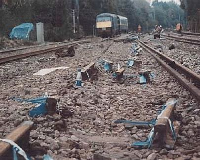
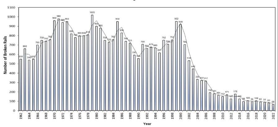
The significant improvement in UK railway safety over the past 25 years has been due to many factors. One, which has not always been widely recognised, is the significant improvements in rail management which reduced the number of broken rails from 952 in 2000 to just 68 in 2021/2022. The impact of the Hatfield train crash on 17 October 2000, caused by a shattered rail breaking into many pieces, drove major changes in the management of the permanent way.
Hatfield
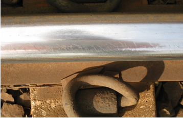
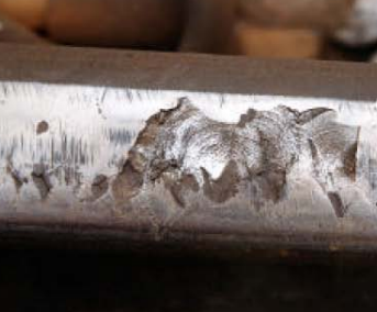
The Hatfield rail break was caused by fatigue cracking, originating from the surface of the head of the rail. This type of defect is known as rolling contact fatigue (RCF) or, when it develops from the gauge corner, gauge corner cracking (GCC). This type of defect usually involves the development of a series of cracks in close proximity which initially form at a shallow angle. If allowed to grow, cracks tend to turn down deeper into the head of the rail. They then can grow quicker and eventually result in a broken rail. As RCF cracks generally develop close together, the rail can, in severe cases, shatter rather than break in a fairly clean transverse break. The close proximity of RCF cracks can also mask accurate ultrasonic signals.
Shattered rails present a greater risk of derailment as the wheel loses contact with the rail head as occurred at Hatfield.
The rail suffered spalling, associated with the RCF which resulted in parts of the upper surface of the rail head breaking out. The spalling meant much of the rail would have been ultrasonically untestable due to poor or non-contact between the ultrasonic probes and the rail. Although the defective rail had been identified, rail replacement was deferred with no mitigation put in place. After this a deferred renewal procedure was introduced to review and mitigate the risks associated with any track renewal not undertaken as planned. New actionable requirements were added to the track standards for ultrasonically untestable rail as a result.
In 1999/2000, 952 broken rails were reported across the national network. This figure had increased from around 670 in 1994 when Railtrack and its maintenance contractors became responsible for the railway infrastructure. Although some of this increase was due to the growth in rail traffic, there were clearly other contributory factors.
Many of the breaks were reportedly due to tache ovale defects, which grow from minute inclusions, typically hydrogen, in the rail steel. However, many of these rail breaks were probably caused by RCF defects, as the quality of steel rails manufactured since the mid-1970s was much improved with very few inclusions and impurities. To the untrained eye, the fracture faces of breaks caused by RCF and tache ovales look similar, especially if the tache ovale defect originates in the head of the rail. As a result, it is highly likely that many of the breaks were misreported as tache ovales, when they were caused by RCF. This misreporting made it difficult to understand the cause of the increase in broken rails.
At the time, there was no national database to record rail defects as each infrastructure maintenance contractor had its own system. This added to the difficulty in carrying out detailed analysis. As a result, on the night of 17 October 2000, track engineers of the maintenance contractors and Railtrack trawled through their individual rail defect databases and records to establish the full extent of known RCF and GCC defects. Until this had been done, the network-wide extent and seriousness of the problem was not fully evident. Even then, there was no consistency as some reported individual cracks whilst others reported clusters or the overall extent (distance) of the cracking.
Response
A few years after Hatfield, the Rail Defect Management System (RDMS) was introduced to standardise the reporting of rail defects and breaks. This enabled a more meaningful analysis of data to be carried out and supported the required rail management processes.
In the weeks following Hatfield, further detailed visual track inspections were carried out across the entire network. These inspections revealed more RCF defects that had not been previously identified. Urgent instructions were issued on the classification of the defects, based upon visible surface crack length and the reporting requirements. These instructions were eventually included in revised rail management Track Standards.
These detailed inspections revealed far more RCF sites than previous records had shown. The urgent rush to reassess these based on the knowledge of that time resulted in many temporary speed restrictions being applied. This had a devastating impact on train services with far fewer trains and greatly extended journey times. As a result, further research took place into the causes of RCF and various solutions. As well as UK rail and metallurgy experts, specialists were brought in from America. The post of Rail Management Engineer was added to focus on rail management.
Railtrack embarked on a huge programme of rerailing using not only British-manufactured rail but also rail imported from various suppliers in Europe.
The research and an enhanced rerailing programme significantly reduced the number of broken rails. However, at some sites, even after re-railing, the RCF returned. Hence a lot more than just rerailing would be required to manage the ongoing issue. The research programmes were key to establishing the further rail management requirements.
Controlling and limiting impact forces
Excessive impact forces were known to trigger rail breaks, particularly if the rail contained a defect or weakness. New, industry wide Group Standards regarding the control of impact forces were issued by the Rail Safety & Standards Board (RSSB) and supported by Network Rail’s own Standard.
From 2000, Railtrack and then Network Rail installed further wheel impact measuring systems which allowed train and freight operators to monitor the impact forces and take action when alarms showed them to be excessive. These were usually caused by wheel flats, hollow, or out of round wheels. Action taken then included inspecting, restricting the speed of the train and, if necessary, removing it from service.
Initial installations were AEA’s Wheelchex system and later installations were a development of the Dutch GOTCHA system. These installations, and the associated controls had an early impact on reducing the number of rail breaks and still assist in managing rail breaks.
Rail grinding and milling
RCF had historically not been considered as a big cause for concern and, prior to Hatfield, there were no control measures in place to control and manage it.
Early analysis, post Hatfield, revealed RCF was less of a problem on routes that were still running mixes of Mk1 style passenger stock and freight traffic. Many of the Mk1 units were fitted with traditional suspension systems and tread brakes, along with the P1 wheel profile.
There appeared to be more RCF on routes with newer rolling stock, particularly when there was not a mix of rolling stock types.
Due to the supposedly “track friendly” design of this new rolling stock, it was not wearing the rail in the same way as the older vehicles. Therefore, when micro surface cracking occurred, it was not tending to be worn away by other wheel sets that traversed the route.
Whilst British Rail (BR) never had a huge rail grinding resource, Railtrack reduced the available resource still further, failing to see its benefits. In the late 1990s, Railtrack had just one Speno 32 stone machine, and that was only in the UK for part of the year. At the time, there was no policy regarding rail grinding and it was certainly not considered for the treatment of RCF.
The railway industry had, inadvertently, allowed the perfect storm to develop with ever increasing fleets of new rolling stock assisting micro-crack generation, whilst reducing the fleets of older vehicles that kept the micro cracking in check whilst Railtrack had reduced rail grinding resources.
With greater understanding of RCF, further rail grinding machine shifts were procured. So too were hand grinding teams that could deal with the shorter lengths of RCF.
After Hatfield, Railtrack invested in 64-stone rail grinders that did not require a possession. By using single pass grinding, as opposed to multi-pass grinding, the process was speeded up with over 20 miles of grinding achieved in shifts. These were often limited by the amount of fire suppression water that could be carried. This was needed to dampen timber sleepers and put out any lineside fires because of sparks. This still compared very favourably to the typical grinding milage of one to four miles that earlier rail grinders achieved, depending upon shift length and the number of passes required to achieve the desired rail profile.
Smaller 32-stone machines were retained for shorter plain line sections and for use on the Southern where the electrified third rail initially prevented the use of in-traffic grinding.
New technology
In 2017, Network Rail procured three new plain line rail grinders from Loram. Two are 32-stone machines and one is a 64-stone machine. These can travel and operate at higher speeds and are more productive than the earlier machines. They also have eddy current detection which is used to optimise the stone settings and grinding requirements.
Network Rail also introduced Harsco Switch & Crossing (S&C) grinders in 2004 for grinding and reprofiling of the rail through turnouts. Network Rail had a lot of vertical switches and crossings which resulted in the wheel/rail contact point being close to the gauge corner, rather than towards the centre of the rail head as is the case on inclined rail which is inclined at 1 in 20. Grinding vertical S&C allowed the contact band to be moved towards the centre of the rail head, reducing the stresses on the gauge corner and improving the ride through the S&C. This reduced the gauge corner cracking and the improved ride reduced track and vehicle impact forces. Network Rail now has five S&C grinders allocated around the network.
Further research developed anti-RCF rail profiles for curves. The profiles were applied by the rail grinders and offered some relief of the gauge corner, reducing the contact stresses on those curves where the profile was applied.

Whilst grinding significantly reduces contract stresses and changes the wheel contact position on the rail head, it can only remove the lightest of RCF due to the limited depth of metal removed by grinding.
A recent development is the greater use of rail milling, which allows the rail head to be fully reprofiled or refurbished, and deeper surface cracking to be removed, which can avoid the need for some rerailing. There are now two rail millers, one Linsinger and one Schweerbau, on the mainline network, plus one Linsinger machine on TfL’s Elizabeth Line.
Rail defect detection
Rail defect detection at British Rail relied very much upon manual pedestrian ultrasonic testing and visual examination, generally carried out by track patrollers, inspectors, section managers or engineers. These found some visual rail defects, but many RCF cracks were very fine and not always visible in certain light conditions.
The ultrasonic testing frequencies were set on historic knowledge of defect and crack growth based upon track categories that considered speed and annual tonnage. Manual testing included probes at 70° (070 test) for plain line head defect detection and 40° (040 test) for detection of cracks emanating from bolt holes. The probes’ ultrasonic signals tended to focus on the crown (centre) of the head and underlying web of the rail. These tests had their limitations and were not always so good at detecting defects towards the gauge corner or field side (outside edge) of the rail head (unless the defects were quite large). Neither would they detect faults in the outer parts of the foot of the rail, or defects in thermit welds.
Towards the end of BR (1993/4) there was one ultrasonic Test Unit (UTU) for the whole network, testing at a speed of 40mph. It could only test plain line and not S&C. Defects reported by the UTU had to be verified by manual pedestrian testing and establish the precise location, and action required. Many UTU defects could not be found. The follow-up testing diverted the hand testing teams from their scheduled testing. It was also disruptive as often 20mph speed restrictions were applied until the defects could be verified and if required, removed. Hence, many track engineers lost confidence in the UTU and, as it was not formally required by BR and Railtrack Standards, its use became limited. However, some track engineers had positive results from the unit, so continued to request its use on an ad-hoc basis.
In 2001/2002 Railtrack required its contract manual ultrasonic testers to introduce Sperry Testing equipment. This began to detect more defects than previous testing equipment.
The Sperry equipment was then fitted on the UTU. It offered wider coverage of the rail head, so was able to detect more defects towards the gauge corner and the field face as well as the crown of the rail head. The accuracy was improved and the number of UTUs increased – initially to three with a fourth added in 2012. As well as ultrasonic equipment, Network Rail’s latest UTUs have laser profiling equipment to measure the rail profile and rail wear. Their eddy current equipment can detect and measure the internal cracks’ lengths in the rail head. This measurement allows track engineers to determine the most suitable solution to remove or manage the defects.
On many routes, manual track inspection has been largely replaced or supplemented by automated inspection.
Network Rail’s New Measurement Train is fitted with a system known as plain line pattern recognition (PLPR) which can identify and record visual rail defects at up to 125mph. Other lower speed vehicles are also fitted with the PLPR system which has improved the consistency of the track inspection process.
Track geometry improvements
There have been significant improvements in track geometry, especially regarding discrete faults. It was established that many rail breaks occurred at discrete geometry faults or dips. The track recorders had the ability to measure these dips, or dip angles, but there were no limits applied to them. As a result, Network Rail introduced limits on dip angles, requiring their rectification within certain timescales, along with other discrete geometry faults. As the overall numbers of dip angles have been reduced, the actionable limits were tightened, especially on the higher category faster routes. This, and the associated change in track geometry standards, has supported the further reduction in rail breaks.
Wheel/Rail Studies and Modelling
Given the seriousness of the issue and the relatively poor understanding of wheel/rail relationships in the UK, the Vehicle /Track System Interface Committee (V/TSIC) was established. This consisted of members of RSSB, train operators, rolling stock leasing companies, rolling stock manufacturers and Network Rail.
They supported the development and the use of computer models that combined inputs from track geometry, speed, and vehicle modelling data to predict where RCF was likely. Track engineers could then use the system to establish what improvements could be made, typically by adjusting the track geometry.They also supported the development of potential changes to rolling stock to reduce RCF, which occurs on wheels as well as rails. These included the development of the P12 wheel profile which was a slight modification to the conventional P8 wheel profile and the introduction of alternative bushes on primary suspension systems to reduce primary yaw stiffness (see diagrams).
Rail steels
Developments were also made in the steel making and rolling processes. The rail at Hatfield was known as Mill Heat Treated (MHT) rail. The head was treated during the rolling and cooling process making it harder wearing. This type of rail became almost standard for track renewals in the Railtrack era. However, it was not fully understood that the MHT rail head was more brittle so when cracks formed, they tended to grow quicker than the normal 260 grade steel.
When this was understood, the initial reaction was to revert to normal grade steel for any rail replacements. However, since then, there have been further developments with rail steels which have assisted in increasing both the longevity of the rail and reducing the wear.
Going forward
With the huge reduction in rail breaks, the UK is now seen as a world leader in rail management. Yet RCF has not gone away and there are still around 60 to 100 rail breaks each year. Many of these are due to undetectable defects when using conventional testing and inspection regimes. These include corrosion pits in the foot, defects in the extremities of the rail foot, and defects within welds. Work is ongoing to establish if realistic systems can be developed to either identify these defects, or the causes of them.
The question needs asking, what is a realistic target for rail breaks? This, of course, will vary from route to route. Only a few years back, 500 and then 300 breaks per year were seen as a huge challenge to meet. Yet, through the introduction of the above improvements, these targets were met and indeed beaten. For track engineers, the challenge is to keep up these improvements. It is unlikely, without huge additional investment and service disruption, that broken rails will be eliminated completely, but those that do occasionally occur, should present a minimal safety and operational risk.