

The re-signalling of the London Underground sub surface routes embracing the Metropolitan, Hammersmith & City, Circle, and District lines is well underway. Collectively known as the Four Lines Modernisation (4LM) project, it is the biggest re-signalling project ever undertaken on the Underground network.
Rail Engineer has reported on the project in the past, first in October 2015 when we gave an overview of the project, and second in January 2018 after a visit to the new Hammersmith control centre and when training of staff had begun. In the five years since then, much of the 4LM project is now in daily use but some of the more difficult sections of line, where tracks are shared with Network Rail and other Underground lines, have still to be commissioned.
A recent talk given to the IRSE London & SE section, by Richard Kirby from Thales Ground Transportation Systems and Sam Etchell from London Underground (LU), explained the progress made and the work still to be completed.
A project overview
Whilst described here as a re-signalling project, 4LM is much more than that. After two initial attempts with supply contracts that had to be aborted for various reasons, a design, build, install, test and commission contract was let to Thales in July 2015 for a value of £760 million. This would be based on the company’s Seltrac system that had been successfully deployed first in Vancouver, then other places around the world, and on the LU Jubilee and Northern lines plus the Docklands Light Railway.
Most of these used a track-based inductive loop system to give positional and command information but the latest variant of the product is now radio based, thus eliminating the need to install wires between the running rails. The 4LM project is using this radio technology so it has differences compared to the other LU lines.
Seltrac comes under the Communications Based Train Control (CBTC) banner and, as well as replacing the existing signalling, it also includes a ‘hands off’ control system with the timetable being used to launch and run trains. For this project, LU has adopted the GOA2 standard (Grade of Operation) whereby trains are automatically driven but with a driver retained in the front cab to start train movement and undertake door control.
The system comes with moving block technology to close up headways when congestion occurs. 4LM has a requirement to handle 32 trains per hour (tph) in the busiest central London sections, amounting to one train every 110 seconds.
CBTC yields many advantages, as follows:
- Optimum operational performance;
- Continuous monitoring and control;
- Automatic Train Supervision (ATS) for the correct routing of trains;
- Makes full use of train performance giving higher speeds with increased acceleration and braking;
- Automatic Train Protection (ATP) to ensure trains do not collide;
- Automatic Train Operation (ATO);
- Full speed protected manual driving.
The extent of the project can be seen in the accompanying diagram which in route mileage terms is nearly half the LU network.
Contract and technical content
The contractual structure within Thales is split between its offices in Canada and the UK. Canada is the design and software hub, and where the various Seltrac systems originate for provision across the world. Thales in the UK is responsible for the interface circuitry, the radio network deployment, all the mechanical engineering aspects, as well as the installation, testing, and commissioning activities.
LU technical staff take on responsibility for system integration with respect to the external interfaces and the training of operators, drivers, engineering staff, and maintainers. LU engineers attend all the test sessions and sort out any abnormalities / problems.
The system architecture is made up of:
- The CBTC system command and management control located at the Hammersmith control centre;
- Vehicle control centres, of which there are 13, that calculate the target running points and times for each train;
- Station controllers that command the devices in the specific areas including axle count evaluation;
- Vehicle on board controllers (VOBCs) that control the train’s systems including propulsion, braking and doors;
- Track transponders positioned at either 25, 50, or 75 metres apart depending on the more accurate positioning required when approaching stations, needing 13,000 for the entire project;
- Radio aerials positioned 200 metres apart giving 1450 radio access points;
- Cabling to connect all of this together, amounting to 5,400 km of different cable types to create a virtual private network (VPN) for communication to the radio access points and all other locations.
System operation, interaction, and integration
To commence a train journey, the driver enters an identity and the train number, after which the command centre automatically initiates the data to be sent to the train containing the route and details for the journey, including the exit from depot tracks. This command message is encrypted and sent via the VPN and the wireless access points. The train receives the message, together with the target point to drive to, and commences the automatic drive via the on-board equipment. Sensor tracking then commences with speed, acceleration, and position being tracked to provide a closed loop control situation. The real-time details of the train movement are displayed to the control operator via the train control monitoring system. To slow down or stop at the target point, both friction and dynamic brakes work together to deliver a load-compensated brake command.
Adhesion control in areas of leaf fall, gradients or wet conditions is needed to ensure the train systems and the CBTC commands work together. Finally, accurate positioning is required to bring the train to a halt within ± 50cm of the stopping point, although ± 1 metre is the safety requirement. Once this is verified, the doors are allowed to open. However, if the train is outside of this tolerance, the doors will not open.
Project roll out
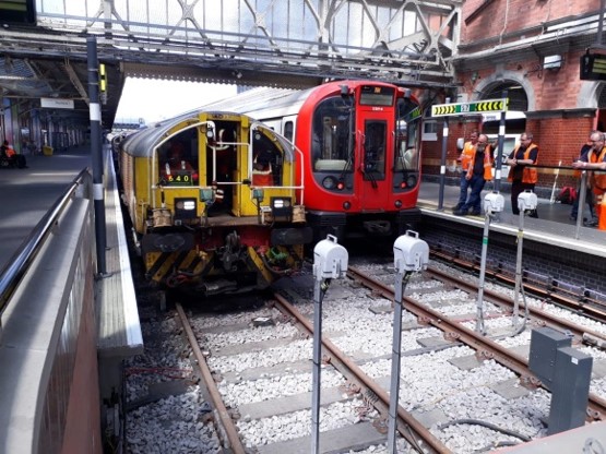
A project of this magnitude could never be commissioned in a single stage. In all, there are to be 14 stages of migration of which eight have been commissioned. The first was, in effect, a test stage from Hammersmith to Latimer Road, a short distance on the Hammersmith & City Line. Not only was this close to the new control centre, it also included the Hammersmith stabling sidings and was not one of the busiest sections. Reversion to the original signalling could be enabled should problems arise. It showed up some of the integration challenges between the S Stock trains manufactured by Bombardier in Derby and the signalling as supplied by Thales. Problems included geographic, physical, and site-based constraints. The stopping command when approaching buffer stops needed improved software to get closer to the buffer stops.
Stage one included extending the system to Paddington once resolutions to these problems were found, and this was combined with stage two from Paddington and Finchley Road to Euston Square thus taking in the junctions at Edgware Road and Baker Street. With growing confidence, the next stage was from Euston Square to Monument and Stepney Green, embracing the Aldgate area triangle.
Stage four extended from Monument to Sloane Square, being relatively straightforward with stage five continuing on from Sloane Square to Barons Court, Fulham Broadway, Olympia, and back up to Paddington. This completed the Circle Line and the complex junctions at Earls Court. It also represented the busiest sections in central London. Stages six and seven extended the District Line eastwards from Stepney Green to Becontree and from Becontree to Upminster.
The remaining stages have still to be commissioned and represent the most difficult as these are where the 4LM trains share tracks with either other LU lines or with tracks shared with Network Rail and other TOC operations. A particularly difficult stage is extending northwards on the Metropolitan Line from Finchley Road to Preston Road, and from there to West Harrow and Moor Park. The line runs in parallel to the Jubilee Line which is also equipped with the Seltrac system so there must be no mutual interference between the two systems.
Problems encountered
The big challenge will be incorporating Neasden depot into the system as this accommodates both Met and Jubilee Line trains. The depot will have three different signalling systems, the earlier Jubilee Line Seltrac, a plc-based interlocking machine for the depot which has linkage to the Jubilee Line system and, still to come, the 4LM Seltrac. The plan is to replace the interlocking with CBTC which then has to partly control the Jubilee Line as well as the depot. Getting rolling stock in and out of the depot under automatic control will be a challenge.
Northwards from Harrow on the Hill, the Metropolitan Line shares tracks with the Chiltern Railways service as far as Amersham. The sections from Moor Park to Watford and from Chalfont & Latimer to Chesham involve only Metropolitan Line trains but on the shared section an arrangement is designed to maintain moving block operation and ATO for Metropolitan Line trains.
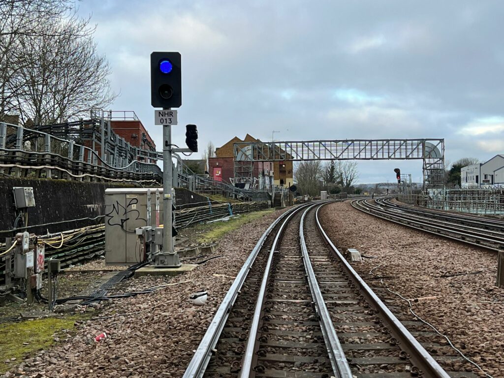
Conventional three-aspect signalling is provided for Chiltern services, but the signal posts will have the addition of a blue light. If the signal is showing red and a Metropolitan Line train is approaching, the blue aspect will be lit and the red light extinguished, thus allowing Met trains to proceed under CBTC and ATO conditions. If a yellow or green aspect is being displayed for other trains, then the blue light is not lit. The system will know what type of train is where on the network. Trip cocks will be retained for both Met trains and those of other operators, mainly for the migration stages but also for operation in de-scoped areas.
Similarly, on the section from West Harrow to Uxbridge, Metropolitan Line trains to Uxbridge share tracks with the Piccadilly line from Rayners Lane. The same signalling arrangement is planned with a blue light aspect provided for Metropolitan Line services. This section may be delayed since, with the recently announced modernisation of the Piccadilly Line, a change may result when the Piccadilly Line is also equipped with a CBTC system.
For the District Line going westward from Barons Court and southwards from Fulham Broadway, it has been decided to de-scope the project. CBTC operation will cease at Stamford Brook and East Putney stations where the driver will change over to manual operation. Thus, the lines to Wimbledon, Richmond, and Ealing Broadway will remain with the existing signalling and trip cocks. The original intention of providing an overlay system to provide ATO has been viewed as unjustifiable at the present time in view of the lower traffic density and the complications arising from joint running with other operators.
The timescale for these further stages is yet to be determined. The Chiltern Railway section has some significant gradients and is in the leafy suburbs, so adhesion control will be all important particularly in the autumn. Real-time weather forecasts will be regularly available and used to adjust the trains’ performance software so as to have less acceleration and reduced braking.
Engineering trains and yellow plant
Clearly, periodic maintenance and renewals will be needed on the various routes, many involving the use of on track machines. These vary in type and include tampers, adhesion sanders, track grinders, battery locomotives hauling wagons, and suchlike. All must be accommodated within the control system which presents some different challenges.
Although axle counters are used as a back up to the normal operation of the control system, and although the data for every train is contained within the VOBC identity, they do confirm whether the passenger trains are seven or eight-car formation. This is less easy for engineering plant as these are of varying length and it is not easy to know where the back of the train is. To resolve this, all engineering trains will have a vehicle equipped with a VOBC at both ends with the 4LM software enhanced to recognise a rear end reported position. There are also reliability issues and how to deal with extended times in section.
Cost, statistics, and project summary
As indicated, the 4LM project in its entirety is a huge project. The total cost is around £5.4 billion, with that including the building and introduction of the new S Stock trains which have been in service for some years, working to the old signalling system. Lots of civil works including the building of equipment rooms have been necessary, plus some track layout enhancements. There are 137 trains of seven-car formation and 59 trains with eight cars. The latter used on the Metropolitan Line. Altogether, there are 1429 vehicles allowing for spares. The engineering fleet amounts to 33 vehicles.
The CBTC element is costing £880 million, roughly a sixth of the total project cost. Not all of this has been spent. The trains had to be retrofitted once the CBTC programme began and this itself represented a logistics challenge. In the central area, the system is capable of having a train arrive at platforms every 110 seconds although, as yet, the timetable is not yet geared up for this frequency. This is a marked improvement compared to the previous service. Overall end-to-end journey times are improved by 5%.
It has taken a team effort to get this far with many complexities having to be resolved along the way. Migrations with the connection to other control systems, roll out and the release of new software to trains, assurance across the work streams including safety, getting user acceptance, and project management are just some of them. The ‘One Team – Shared Office’ ethos has enabled an optimum team effort. Although the project has not met its original timescale, the benefits of the commissioned sections are there to be seen.
Rail Engineer will track the introduction of CBTC to the remaining sections of route. Watch this space.