

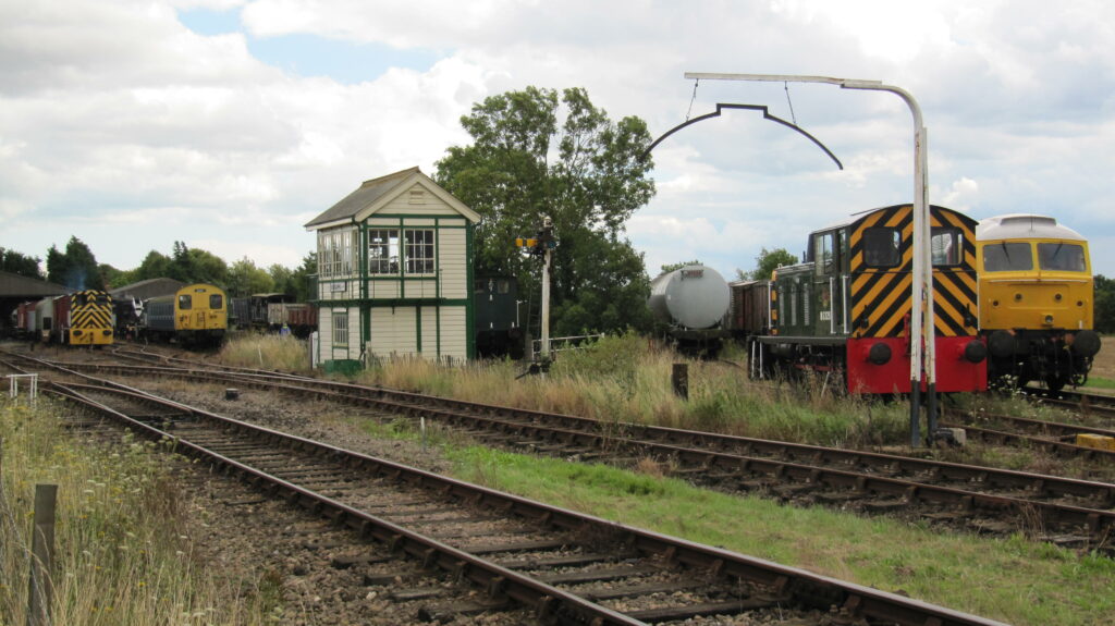
Early railways were built for freight; passenger traffic was a slightly unexpected bonus. Engineers had to be sure that the goods on trains would fit through tunnels and under bridges and the concept of the load gauge was born. It was an inverted semicircle of metal hung at the maximum permitted height located near the exit of freight yards. The deal was that if the train fit under this hoop and all loads were within the maximum width of the wagons, the train would fit the infrastructure. The infrastructure managers had to keep their infrastructure outside a larger envelope known as the infrastructure gauge. The difference allowed for dynamic movement of the train plus a tolerance.
But not all railways were built to the same infrastructure gauge, causing problems when through running started. These issues have been compounded since the Channel Tunnel was built because virtually all European 1435mm track gauge railways have a larger vehicle profile than the UK and the Tunnel itself is bigger than either of them. One only need to look at a EuroTunnel double deck car transporter train to see the different gauges. The locomotives are to the small British gauge with a high reach pantograph, and the wagons are to a special large gauge to accommodate cars and enable people to move around during their journey.
Since the birth of railways nearly 200 years ago, demand for bigger and bigger loads has put pressure on the early concept and more scientific methods for assessing whether a vehicle/loaded wagon would fit were it developed. But the loads continued to grow, leading to many routes being enlarged to accommodate bigger loads, especially containers. It should all be reasonably straightforward if the infrastructure and trains people are working together to deliver the best outcome for the railway. But over the last 25 years, the situation has become more complex. Train operators still have to make sure their trains fit the infrastructure and the infrastructure manager still has to make sure that the infrastructure will not be struck by trains, but neither party has overall responsibility for the outcome.
Setting the scene
This preamble sets the scene for a seminar on Railway Gauging organised by the Institution of Mechanical Engineers in March 2023.
Tim Shakerley, former managing director of Freightliner, gave the keynote address. He outlined the environmental benefits of rail freight – even when diesel powered – and reminded everyone that rail freight is carried on a commercial basis in competition with road transport. In effect, road transport rates set rail freight rates, and rail freight businesses have to be responsive. If a potential customer wants to transport a train set of containers over a new route, then an answer typically has to be given within seven days. This is a considerable challenge to the current gauging process which can take weeks to provide an answer.
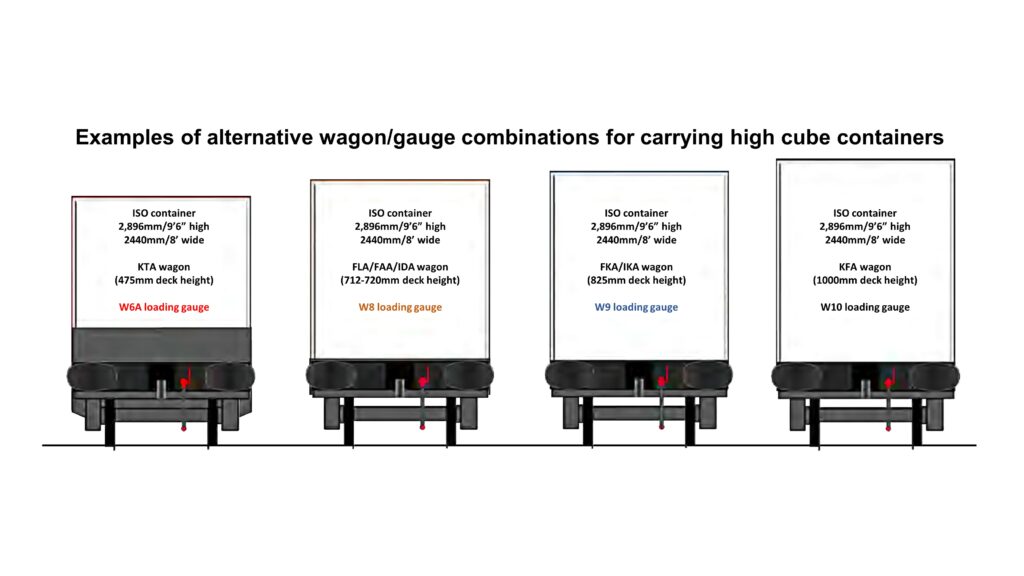
Richard Moody, Programme Director for Freight Reform in the Great British Railways Transition Team (GBRTT) took up the story outlining how the infrastructure has been modified to accommodate modern containers carried on more track friendly bogies. He outlined the various sizes that need to be considered and highlighted a unique constraint of the UK gauges – that the lower section below about 1100mm above rail height is narrower than above and much narrower than is usual in Europe.
He also showed an example where a gauge has been enlarged for a route but what might be seen as a diversionary route has not been cleared. This leaves the signaller having to know that some trains cannot be diverted, although mistakes can be made.
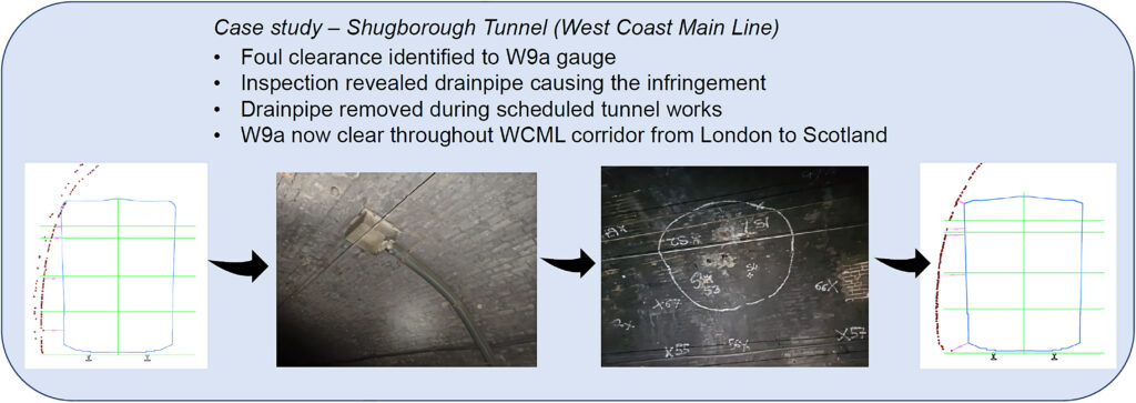
Another issue he highlighted is that the gauging database might show a route as not clear but not why. Sometimes the change to enable clearance for a larger gauge might be very simple as shown in the above illustration.
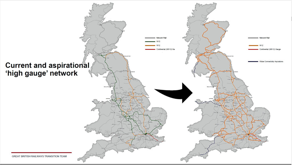
This often takes time and certainly doesn’t meet the time aspirations outlined by Tim Shakerley. Richard illustrated the progress in delivering W9a and W12 gauge clearance on parts of the network but said that a more strategic approach needs to be taken, and he presented an aspirational future freight network.
The subsequent presentations clearly illustrated why a strategic network of freight routes cleared for the largest wagons might be desirable.
Gauging basics
There are two key players involved in agreeing gauge compatibility: the Train/Freight Operator and the Infrastructure Manager. Each party has to satisfy itself that the vehicles and infrastructure are compatible. Three gauging methods are available:
Reference gauging
This involves demonstrating conformance to a declared vehicle gauge and proposing operation over a route published as compatible with that gauge. This is what a freight operator would normally seek to do. A wagon and container that is demonstrated to comply with, for example, W9 standard freight gauge (see GERT 8073 issue 4) would be deemed to be fit to operate on sections of railway infrastructure cleared to W9 gauge. This approach is generally reserved for freight but has been made more complicated by the introduction of variations such as track friendly bogies which challenge many of the assessments made when the ‘W’ series of freight gauges were developed.
Comparative gauging
This process requires demonstration of compatibility of the candidate vehicle via a valid comparator which already operates over a route in significant and regular, incident free, operation. This generally means measuring the dynamic envelope of the existing vehicle and demonstrating that the candidate vehicle is within that envelope at all times. It requires a great deal of information about the existing vehicles and infrastructure. Sadly, comparative gauging is fraught with difficulties as the comparator vehicle is generally only accorded ‘grandfather rights’. Even though the existing rolling stock has run safely for years, often there has been no recent assessment of what clearances actually exist.
Absolute gauging
All new passenger types use this process. The reference passenger gauges, PG1 (20-metre vehicles), PG2 (23 metre) and PG3 (26 metre) which were intended to facilitate easier gauging for passenger vehicles, are smaller than the trains people want (by definition, they represent the smallest ‘through routes’) and no trains have been built to them because appendages, such as footsteps, are not included; largely because of the diversity of platform positions. It involves demonstrating compatibility over a given route by calculating clearances against surveyed structures and other vehicles on that route for the maximum speed of the route or vehicle. So, all passenger trains are individually, absolutely gauged.
As Dr David Johnson observed in conversation, the process is not expensive these days, but the issue is that removing the occasional obstruction falls upon the operator to fund, even though the benefit will be enjoyed by any operator that wants to take advantage of the clearer route. Indeed, one supplier told Rail Engineer that it had spent an eight-figure sum on removing infrastructure obstructions for its recent train introductions.
Sometimes it is necessary to use combinations of these approaches. If, say, a route is generally clear but some surveys of particular ‘tight’ locations are required, the tight spots can be assessed against actual movements at that location; e.g., on straight track, it may be determined that maximum lateral movements will not happen, allowing an otherwise tight clearance to be deemed satisfactory.
Demonstrating compatibility
Dave Galloway, Network Technical Head, Systems Compatibility and T&RS, Network Rail, described demonstrating network compatibility. The requirements for demonstrating network compatibility are laid down in Industry Standard RIS-8270-RST. This provides a standardised approach to demonstrating compatibility of vehicles and infrastructure. Before granting authorisation for placing in service, organisations have to check that new, upgraded, or renewed vehicles or structural subsystems meet ‘essential requirements’.
These requirements cover compatibility between vehicles and infrastructure with respect to safety, reliability and availability, health, environmental protection, technical compatibility, and accessibility to persons with disabilities and/or reduced mobility. This means demonstrating that the systems assets or vehicles comply with applicable National Technical Specification Notices (NTSNs) and Group Standards. This requirement does not apply to cascaded vehicles and more minor changes to infrastructure assets.
For all changes, it must be demonstrated that vehicles are technically compatible with the infrastructure on which they will operate, and the infrastructure is compatible with the vehicles and with adjacent parts of the infrastructure where the new infrastructure is constructed. All changes must also be safely integrated into the overall system, and not create unacceptable risks.
As Dave said: “all these options require co-operation between parties,” and with suppliers, consultants, and approval bodies in the mix there can be quite a lot of ‘parties’. The detail of compatibility is beyond the scope of this article, but RIS-8270-RST is well worth a read.
Standards and challenges
Barry Tan, Principal Vehicle Dynamics Engineer at RSSB described the current regulatory and standards framework and the 16 standards in categories Infrastructure, Rolling Stock and Plant, and Energy that contain requirements related to gauging.
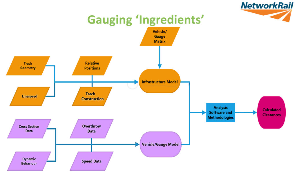
He illustrated typical vehicle gauges and how these are recorded in Sectional Appendices. He outlined the basic gauging process (Gauging ‘Ingredients”, below) and the importance of understanding the implications when the assessment indicates a foul, such as a relatively trivial overgrown bush or a not so trivial platform.
Barry moved onto the special challenges with the platform train interface where there are three NTSNs, nine other Group or Railway Industry Standards, and two Guidance Notes relevant to the PTI. Barry said that in most places, the larger the gap between the infrastructure and the train, the better, but this rule of thumb doesn’t work at platforms where there are conflicting requirements.
The standard platform height is 915mm and offset from the nearest rail is 730mm (increased up to 820mm on curved platforms), but Barry reported that just 7% of platforms conform to both these dimensions. He highlighted Industry Standard RIS-8273-RST which includes guidance on using gap fillers.
Computer models
Until recently, the gauging process has used a model of a vehicle outline enlarged to take account of dynamic movements, together with centre and end throws to be used on curves. The computer models used take a very basic view with ‘empirical probabilistic assumptions’ that ‘maximum vehicle movement’ is a mean +2.12 standard deviations when it is known that a mean of +4.5 standard deviations can occur. The former is taken because some events are unlikely to occur at the same time as others. David Johnson, founder and Technical Director of D/Gauge showed that there is an even more scientific way using real rather than assumed probabilities. He said that all the worst-case tolerances are unlikely to occur at the same time and D/Gauge software uses Monte-Carlo simulation to assess the probability of varying combinations of movements, i.e., inputs to the model. For example, input 1 might have an absolute value of -11mm whereas in reality its movement is a normal distribution with a mean of 0mm and a range of +/- 20mm.
Whereas input 3 might have an absolute value of -6 mm but, in reality, has a linear distribution over a range from -6mm to 0mm.
Illustrating this a different way, for vehicle loading, absolute gauging considers only tare or crush load and no intermediate conditions which is overly conservative. Probabilistic gauging considers an equal likelihood of loading at each state from tare to crush and the vehicle behaviour is matched to the intermediate loading conditions. Similarly, in absolute gauging, suspension is considered to be either inflated or deflated whereas for probabilistic gauging it works with 99% inflated and 1% deflated. It also takes a more accurate view of centre and end throw. Probabilistic gauging, using multiple simulations with multiple inputs, produces a clearance histogram and, where a chance of a Foul exists, a probability is provided.
David illustrated the approach with platform-train clearances between a class 357 unit and Pitsea Platform 2. Conventional techniques predicted a Foul, whereas the probabilistic approach demonstrated a small clearance falling into the Specially Reduced Clearance category with a 0.00001% risk of a strike even with deflated suspension.
It has also demonstrated huge infrastructure cost savings for Network Rail in Scotland with electrification clearances. But, so far, no one has published a standard saying what ‘benchmark’ parameters should be used across the industry.
Gauging database
Any gauging technique requires accurate information about the vehicle and the infrastructure. The former can be modelled, and the model largely validated in a workshop. In contrast, the infrastructure is much harder to assess and does change with time. Network Rail has long had the objective of an accurate, up-to-date national gauging database and Rebeka Sellick, Development Director of Cordell.ai presented the emerging new Railway Gauging Database Solution. This solution will capitalise on modern ways of collecting Infrastructure data and uses more sophisticated methods to store it.
Rebeka described the old world: legacy clearance systems; vintage and proprietary software; siloed data, manual processing which is slow and costly; and a mix of too much & not enough data. She contrasted it with the ambitious ‘New World’ objective:
- Intelligent clearance systems
- Version controlled accurate data
- Audit trails
- Digital network model
- Accurate location
- Frequent surveys accommodated
- Integration, including Application Programming Interfaces (API)s to allow others to construct applications to use the data
- Transferable, open data formats
- Obsolescence proof
- Making automation business as usual
- Trusted intelligence.
The aim is to have quick survey uploads that would allow assessments in minutes, not months. It would include location specific information for tight clearances including pictures to allow the nature of substandard clearances to be identified without the need to go to site.
Rebeka demonstrated samples of output and forecast user acceptance testing in May, with go-live in August 2023.
Vehicle Dynamic Modelling
The final presentation was given by Ian Hills, technical director at Atkins who outlined the capability of Vampire modelling. Vehicle dynamics is the study of masses in motion and covers modal frequency and damping, ride quality, derailment risk, wheel and rail wear, and gauging, among other things. It is the process by which the static envelope of the vehicle is enlarged to take account of suspension and other movements, a complex subject, needing specialist software such as Vampire.
Vampire – now known as Vampire Pro – is a multi-body simulation package that has been developed and optimised specifically for railways. It enables cost-effective analysis of rail vehicle/track performance and safety through simulation. Users can build dynamic vehicle models and study the response of the vehicles to measured track geometry or other user-defined inputs and external forces. It takes the vehicle model, wheel-rail contact model, and receives track input data to deliver a variety of outputs such as vehicle movements and wheel-rail forces. Vampire Pro has a long pedigree, having originally been developed by BR Research over 40 years ago.
Many parameters have to be considered in building the Vehicle Dynamic Model including: dimensions and shape of the vehicle; its dimensional tolerances and allowances; component wear; deflection and bending due to static load; movement due to quasi-static acceleration such as steady-state curving and on canted track and movements due to dynamic effects of track; overthrow of vehicle cross sections on curved track, lateral position of wheels within the track and movements due to wind loads. Models also have to be aware of infrastructure issues such as: track curvature, cant and line speed, track tolerances, allowances and wear, structure shape and positional tolerances, and clearance requirements. These inputs can then be used in Vampire to create the movement tables and other movement data that underpins all modern gauging models.
Conclusion
The seminar provided an insight into the process of gauging and how the availability of information and the techniques are improving. That said, thinking of Tim Shakerley’s presentation, it appears to Rail Engineer that we are still some way from responding to Tim’s requirement that if a Freight Operator wants to transport a train set of containers over a new route, then it needs an answer within a week, otherwise the loads will probably travel by road. As such we applaud Richard Moody’s proposal for a strategic freight network cleared to W12 gauge although David Johnson observed that the W12 gauge was developed some 30 years ago and takes no account of wagon developments and the likely loads.
David said: “You are unlikely to be able to run 9’6” x 2600mm containers on modern, track-friendly suspensions with 1000mm standard deck height within W12 gauge. In short, W12 is out of date and planning to use that going forward will actually fuel the demand for absolute gauging on the next generation of wagons/load combinations.”
Tim Shakerley added: “If we can really use the emerging Railway Gauging Database to get real time, up to date data on the network (i.e., not influenced by maintenance change), we can really identify if clearance is constrained by a tree branch or a tunnel, and then quickly implement a probabilistic gauging analysis to see if it will really fit (almost all freight wagons built since 2000 have validated Vampire models), just maybe we can go to new places at a pace that will allow freight to truly compete with road!”
And finally…
Rail Engineer has spoken to a number of people involved in gauging, or who have considerable influence on the solution. There is a considerable divergence of opinion ranging from “gauging is simple”, through to “gauging is hard”. Whilst metros might be able to define a standard size linear ‘hole’ though which the train must run, doing the same on the much more extensive national network is far less straightforward. To do so would be to spend a great deal more than is necessary or to use vehicles that are much smaller than are in use today.
However, with probabilistic gauging techniques, good vehicle models, and an accurate infrastructure database, there seems to be some confidence that gauging can be carried out quickly enough so that one further obstacle is removed to allow freight operators to compete with road. But it will require whole industry co-operation and a big push to get there.