Home Blog Page 135

Thameslink Telecoms

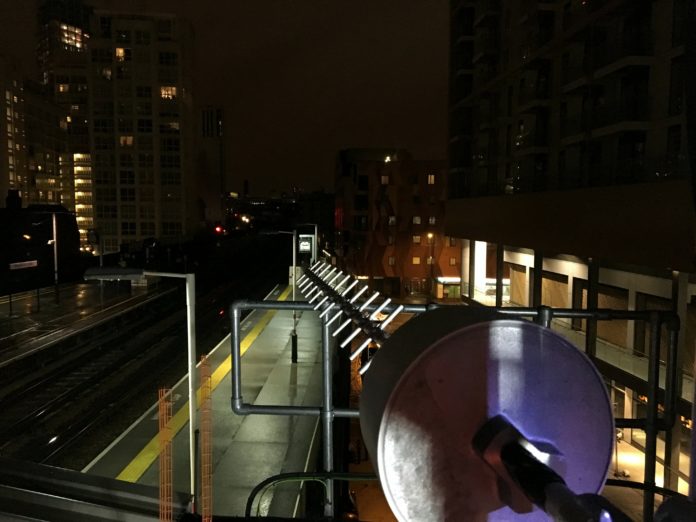
Antennas at Elephant & Castle.

The Thameslink north-south rail link across London is nearing fulfilment. Despite the timetable problems back in May 2018, the enhanced capacity on the route is already easing the daily commutes for thousands of people. When it reaches its full potential of 24 trains per hour (tph) in each direction through the central London core, an even bigger demand is to be expected.

The overall programme, covering five route areas, will have cost £4.6 billion, including the provision of 55 new 12-car and 60 eight-car trains, running through 10 signalling centre areas of control on track used by 11 train operating companies (TOCs).

Much of the project’s glamour has focussed on the new stations (London Bridge and Blackfriars in particular), its civil engineering, especially the Bermondsey flyover, and the new ETCS with ATO (European Train Control system with Automatic Train Operation) train control system. There has been very little mention of the telecommunications network, without which none of the above could have happened. Yet all the telecoms requirements have needed a massive design and implementation project that has equalled the other disciplines in the need for creative thinking and new ways of providing service.

To understand what has been involved, the London & SE section of the IRSE hosted an evening meeting in January whereby Network Rail could demonstrate just how complex and wide ranging have been the telecom elements. Rail Engineer went along to learn more.

Upgrading GSM-R

Whilst the Thameslink routes both north and south of the Thames and through the central core had been equipped with GSM-R, this was primarily associated with driver to signaller voice communication. As such, the capacity, coverage and resilience of the radio network was less than would be required if used as a bearer for ETCS. An upgrade has therefore been necessary – the responsibility of the telecoms function within Network Rail for the control and infrastructure equipment but also involving the TOCs for the ETCS train-borne mobile equipment.

The ETCS/ATO area extends from Kentish Town and Canal Tunnel junction in the north to Elephant & Castle and beyond London Bridge in the south. To improve the robustness of the system, most of the previous radio cells have been split with 15 new Kapsch 9000-series base stations being purchased to replace the existing nine Kapsch 8000-series units.

All base stations now have a double landline connection, the majority using diversely routed fibres plus a 12-hour standby power supply at each site. Much of the central core section is equipped with radiating cable and 16 radio cable repeaters are needed to keep the signal strength at the required level.

GSM-R radio performance has to take account of the channel availability within the 4MHz uplink and downlink allocation. This leads to two constraints.

Firstly, in congested areas like London where multiple rail routes are in close proximity, channel allocations, base station locations and aerial alignments have to be carefully planned to eliminate, as far as possible, the risk of co-channel interference.

Secondly, whilst having a circuit switched connection (an individual train seizes and holds an available timeslot for the duration of use) is just about ok for occasional voice traffic, the data requirements for ETCS operation mean that a continuous connection is required. With circuit switching, there is simply not enough capacity within GSM-R.

Fortunately, development and proving work in the UK and Europe has determined that packet switching is an acceptable alternative for the future. Even if the occasional packet is lost, the data transfer is sufficiently guaranteed for reliable ETCS information updates as well as enabling a considerable increase in capacity.

The upgraded GSM-R network has been extensively tested, both for coverage and resilience. Additional hardware duplication has been provided to minimise the chance of equipment failure that would result in ETCS data being unavailable. An additional feature with the new Kapsch base stations is a Voltage Standing Wave Ratio alarm, which monitors the radio signals such that any deviation from the norm is detected before a fault actually occurs. The overall monitoring of this, and indeed the nationwide GSM-R network, is undertaken by Network Rail Telecoms (NRT) from its Network Management Centres.

King’s Cross fire of 1987.

Emergency Services radio

The King’s Cross fire in 1987 (above) brought home the need for the emergency services to communicate together effectively in all locations, including underground railways. Since Thameslink in largely underground in the central core, provision has had to be made to enable radio systems covering police, fire and ambulance services to communicate in any emergency circumstances.

Using Tetra technology in the UHF band, all police forces (including British Transport Police – BTP) and the ambulance service have now converted to Airwave, which is the same technology that London Underground uses for its track-to-train communication. Providing Airwave coverage on LU is therefore relatively straightforward. Adjacent LU and Thameslink locations get coverage by default, but, elsewhere on Thameslink, it has been necessary to feed Airwave signals down the same GSM-R radiating cables, but with different types of repeaters.

The fire service has continued to use a different system – Fire Ground – which again has its signals injected into the same radiating cable. The Fire Ground system had already been provided in the St Pancras area as part of the HS1 communication requirements, so this system was extended into Thameslink to prevent inter-channel interference. The erstwhile York Way tunnel at King’s Cross has been retained as an access point for the emergency services.

Traffic Management

The crucial need for a traffic management system (TMS) to regulate the Thameslink train service through the central core when 24tph eventually happens was described in issue 160 (February 2018). Using the Hitachi Tranista system, this will look at real-time train movements from as far away as Luton and Hitchin in the north and Sevenoaks and Three Bridges in the south, and to then constantly calculate the optimum pathing of trains should any of them be running late and not arriving at the central core in the timetabled order.

Getting TMS to be effective is a complex challenge and demands crucial telecom and data links as part of the design.

Such is the foreseen dependence on TMS that two parallel systems have been procured (A and B) to provide the necessary resilience. Capturing the constant stream of data from all the outlying locations has meant the provision of two independent Ethernet rings of 250Mbit capacity to deliver the train running information. The FTNx fixed telecommunications network provided by NRT (Network Rail Telecoms) as a nationwide IP (Internet Protocol) data service has been employed for this task. This means that all TMS data is IP-based, which was a logical way forward in any case.

As traffic management systems spread to other areas of the country, so the Thameslink TMS system will link into these and thus potentially provide train running information from even further afield. Whilst the output from TMS is an advisory tool to the signallers, who will be able to change the routing plan if they think it advisable, eventually TMS will link into the ARS (Automatic Route Setting) facility within the rail operating centres (ROCs) and thus set train paths automatically. The signallers are to be provided with web-based Train Graphs at their workstations so that they can see the overall train service performance at a glance.

The Signalling Bearer Network

Antennas at Elephant & Castle.

Not only is a comprehensive telecom and data network required for TMS, but the very extent of the Three Bridges ROC operation means that similar connectivity would be required for controlling all the outlying signalling equipment. Traditionally, this would have been done by low-speed data links provided as part of the signalling design, but the cost of such a provision would be considerable and questions were asked as to whether a more cost-effective solution could be devised.

The resulting specification called for a comprehensive fibre and data communications network (DCN) and, with the FTN network already in place, using this was an obvious choice. However, just taking the available bandwidth without any provision for local control gave a measure of unease and thus a compromise was needed.

A joint development between Siemens, Network Rail and NRT came up with a solution that effectively delivers a virtual private network within the FTN backbone. Three pre-assessments were identified:

  • Diversity needed for all required service functions to each relay room;
  • The level of availability and path length from the FTN to each relay room to be scored;
  • A comparison of options to be made with identification of any diversity shortfalls.

The resultant network has moved the Network Terminating Point (NTP) from the FTN router to the signalling equipment rooms, with an independent network control centre established at Three Bridges working in conjunction with NRT. The DCN has been renamed TSPN (Thameslink Signalling Private Network – known colloquially as Teaspoon) and gives four independent paths from the main signalling equipment rooms back to Three Bridges ROC.

Every signalling trackside module has an IP address layered to SIL4 (safety integrity level 4) standards. Close co-operation has been needed with the NRT control centre staff and this involved considerable training to ensure familiarity with the critical network requirements. 140 routers are employed to start with, and more will be added once the Hither Green area is converted.

Since start-up four years ago, only two faults have been recorded, one a power supply problem, the other a router failure, neither being service affecting.

Station Information and Security (SISS)

All stations in the central core need to give out comprehensive information to the passenger plus sophisticated monitoring of security. Included within this are customer information screens (CIS), public address and CCTV.

During the early stage of the project, the displaced CCTV recording equipment from King’s Cross was relocated to London Bridge, so that output from the existing 400 analogue CCTV cameras could still be recorded. These cameras were connected to the new information network by the use of analogue-to-digital converters, prior to them being replaced during the rebuilding.

At London Bridge, new equipment has been provided throughout, based upon an IP station data network consisting of two-core switches forming two VLANs in ring formation. Connected to this are 700 new high-definition Bosch cameras, with recording equipment to match, plus a video wall in the control room. The cameras are also viewable from Three Bridges ROC and the BTP control room at Victoria.

Departure infomation at London Bridge

A total of 310 CIS train departure screens using Infotec LED displays are provided across all platforms. New PA amplifiers link into the system but include a hard-wired voice alarm facility to ensure availability in any emergency situation.

Achieving the 24tph throughput in the central core requires critical control of station dwell times. These are timetabled at 60 seconds, allowing 42 seconds for passengers to alight and board. Automatic door opening is employed but CIS information is crucial to conditioning passenger behaviour.

Train summary displays are provided showing the time until the next train and the six subsequent trains. These use TFT (Thin Film Transistor) technology, with past concerns over display life having largely been overcome. Alternate units go into ‘sleep mode’ at night to prolong life.

Still to be commissioned is an overall integration and monitoring system for all the Thameslink central stations. A contract is in place with Telent for the provision of its MICA (Management, Integration and Control of Assets) product, with the hardware already installed at Three Bridges. Used previously at Clapham Junction and London Bridge, the system will give visibility of all telecom facilities at every station.

In addition to CCTV, PA and CIS, the system will monitor lighting, lift and escalator alarms, station radio, security and fire alarms, and will also monitor dwell times and passenger congestion, with an alarm being generated if limits are exceeded. The benefit of MICA is that different manufacturers’ products can be monitored, regardless of type and age, thus avoiding the replacement of assets that still have useful life.

In this modern age it is a commonly held view that telecoms will just be there, akin to water in the pipe and electricity at the socket. If nothing else, this account shows just how complex the provision of telecom facilities is on a route such as Thameslink.

Thanks to Tom Chaffin and Stephen Brown of Network Rail for delivering such an elucidating explanation.

Evolution of signalling

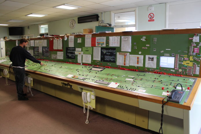
Swindon panel, seen here in 2014, is now preserved at Didcot Railway Centre.

The advancement of signalling has been driven by the need to control train movements in the most efficient manner whilst optimising the capacity of a given layout configuration. Progress has been achieved as a result of technological developments, new legislative requirements, and the all-important lessons learned from accidents and incidents. This article introduces a major new book that charts the evolution of signalling, and also indicates some additional sources of technical information about signalling for those wanting to learn more.

Signalling in action

Network Rail has about 40,000 signals across the whole network, controlled by a variety of mechanical, electrical and computer systems, mostly behind the scenes. The signalling system in live action may be observed on Open Train Times (www.opentraintimes.com) and other similar websites that provide a much-simplified version of the workstation or control panel that the signaller is operating to control train movements. 

Watching complex areas such as Liverpool Street and London Bridge during the peaks, it is difficult for the general user to appreciate the vast amount of complex technical kit that provides for the safe separation of trains and intense working at busy junctions and in station areas. Robust safeguards are built into the interlocking to prevent signaller error compromising safety.

The driver hasn’t been forgotten

Integral to the signalling system, driver aids such as the Automatic Warning System (AWS), and Train Protection Warning System (TPWS) play their part to ensure driver compliance with signal aspects. 

Automatic Train Protection (ATP) systems overcome weaknesses in the AWS/TPWS combination by continuously monitoring train speed and automatically implementing corrective action should a driver fail to comply with signal aspects or speed limits. 

Free standing ATP ‘trial’ systems are in operation on the Great Western main line and the Chiltern line. However, ATP is a component of the European Train Control System (ETCS) that Network Rail is gradually implementing. These vitally important safety systems have been introduced in response to lessons learned from train accidents. 

20-lever frame at Acle signal box, Norfolk.

Not so modern

In the modern age of personal computing, consisting of devices that are ‘upgraded’ every few years, newcomers to the industry may be surprised that train movements in some areas of the country, including the busy West Coast main line in the Stockport area, are still controlled by nineteenth-century technology, with signallers pulling levers. Elsewhere, mid-twentieth-century control panels are still in service, with signallers pressing buttons to set routes. Computer control is being increasingly implemented since the first digital Solid State Interlocking (SSI) was commissioned at Leamington Spa in 1985, but conversion of the whole network is a long-term project.

So how has it come about that we have such a diverse range of technology in use today? 

Funding constraints and longevity

Many a proposed scheme has had to be de-scoped when money has run out. For example, mechanical lever frame signal boxes continue in service at Clacton and Stockport, interfacing with adjacent modern signalling centres. Even in the 1960s, new power box schemes were opened controlling a reduced route mileage compared with what was originally planned. 

Towards Stoke-on-Trent via Uttoxeter was excluded from Derby Power Box, as was the Northampton loop from Rugby box, although the latter was incorporated some years later. A mid-1980s resignalling of Shrewsbury was shelved leaving the lofty 1903 LNW tumbler frames at Severn Bridge Junction (180 levers) and Crewe Junction (120 levers) still in service today! 

Despite predictions to the contrary, the skills of the mechanical locking fitter are still with us today, and points and signals operated by metal wires and rods are more durable than those controlled by electrical wiring, the insulation of which may degrade over time.

Workstation at Saxmundham, Suffolk.

Staff professionalism

Signalling must be designed, installed, tested, commissioned and maintained by staff working to high professional standards in compliance with a series of specialist internal company standards issued by Network Rail. Staff competence is also vitally important and signal engineers are required to hold an Institution of Railway Signal Engineers licence for the category of work that they undertake. 

The various factors described above contribute to the overall cost of signalling. It has always been challenging for the industry to justify that the capital cost of signalling improvement schemes will achieve payback in some way such as staff and maintenance savings, or improvements to capacity. 

The way in which various factors, including those described above, have played a part in the continuous improvement of signalling since the early part of the nineteenth century are described in a new book – A Chronology of UK Railway Signalling, 2nd edition.

This monumental hardback tome of nearly 500 pages from Peter Woodbridge and his contributors provides a fascinating insight into the evolution and innovation of signalling from the invention of the Leyden Jar (capacitor) in 1746 to the fibre-optic axle counter sensor of 2017. This chronological synopsis of significant events in the development of railway signalling covers all UK railways but concentrates on ‘mainline’.

The one-line event index, split into categories such as accidents, block working, companies, land legislation, is listed in chronological order, acting as an at-a-glance evolution summary and directing readers to the appropriate year in the main body of the chronology. Here, the aim is to present the overall story of the evolution of all the elements that comprise railway signalling and give the general ‘big picture’ of how, through innovation, accidents, legislation and pure chance, we have today’s signalling.

The story starts with the Stockton & Darlington Railway of 1825 and an early attempt at providing signalling comprising braziers (fire baskets) into which burning coals could be hoisted as a stop signal. The section concludes with fifteen entries for 2018 including accidents at an AHBC (automatic half-barrier crossing) and a UWC (user-worked crossing) and, more positively, the first Automatic Full Barrier Crossing Locally monitored (AFBCL). 

Two short sections describe the development of the former Western Region’s E10k relay interlockings, and Geographical relay interlockings used elsewhere, many examples of which are still in service including the 1960 Plymouth Panel Box, and 1966 Birmingham New Street station area Westpac MkI interlocking.

The final section contains an extensive thought-provoking summary of significant accidents spanning 162 years involving signalling design, operation, maintenance and modification. The lessons learned have shaped today’s signalling system, which plays a vital role in the safe and efficient working of trains. However, the recent collision at Waterloo is a wake-up call that the causal factors identified in past accident investigations must not fade from the industry’s collective memory.

The book concludes with a selection of colour photographs illustrating Peter’s signal engineering life.

Technical terms are clearly explained making it an easy read suitable for a wide audience. At £30 plus postage it is NOT currently available from online retailers. Proceeds go to Swindon Panel Society, which has preserved the Swindon Entrance Exit (NX) panel at Didcot Railway Centre with train movements, control and indication of outdoor functions such as points and signals simulated by computers. 

If you wish to purchase a copy please contact Peter Woodbridge, either through the Institution of Railway Signal Engineers, 4th Floor, 1 Birdcage Walk, London SW1H 9JJ – 020 7808 1180, or by emailing the author – [email protected]

And there’s more…

For those interested in learning more about signalling, there are various resources available:

British Power Signalling Register 

This free online resource, fully updated in January 2019, is produced by Andrew Overton and hosted on the website of the Signalling Record Society (www.s-r-s.org.uk/archivebpsr.php). The documents are aimed at signal engineers but will be of interest to anyone wanting to know more about power signalling.

The first component is a PDF document providing a comprehensive introduction, glossary and detailed explanations of interfaces, power frames and interlockings, concluding with a colour pictorial guide to interface and interlocking designs. The register itself is an Excel spreadsheet with three tabs ‘Interfaces’ (signal box or workstation), ‘Interlockings’ and ‘Power Frames’, the compilation of which evidently involved extensive research since coverage includes all power signalling equipment commissioned in Britain from 1883 to date excluding London Underground and metro networks.

For the technically minded

For those with a thirst to learn more about the technical aspects of signalling, the following text books are available from the Institution of Railway Signal Engineers (www.irse.org): 

  • Railway Signalling – Although published in 1981, it is still relevant today with descriptions of the principles of signalling layout, interlocking and controls. Relays, points, track circuits, remote control and train describers are covered.
  • Railway Control Systems – This sequel from 1991 includes Solid State Interlocking (SSI), Single line working, level crossings, operator interface and Automatic Train Protection.
  • Railway Signalling and Control – This further sequel brings the story up to 2014 and includes the various computer based interlockings, axle counters, point operating mechanisms and stretcher bars, AWS, TPWS, Tilt Authorisation and Speed System (TASS), ETCS, HS1 signalling, and signal sighting.

Rail Engineer

Of course, you can just continue to read your favourite railway engineering magazine Rail Engineer. Almost every issue contains at least one article on railway signalling, its technology and concepts, and these are reproduced online on this site.

The management of railway incidents

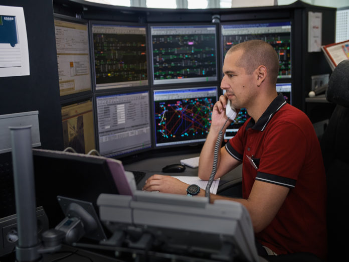
ÖBB control centre. (Frequentis)

No matter how reliable or how safe the railway becomes, incidents will always occur, be they related to weather, safety, technical or human problems. Many of these will be trivial, some will be serious, a few may be catastrophic, but all have to be managed effectively and professionally in order to get the railway re-opened and the trains running again as quickly as possible.

All railways have contingency plans – some appoint on-site controllers, others produce an emergency procedures handbook, some have specialist teams for technical troubleshooting, many have a combination of these with reviews taking place on effectiveness after any major incident.

Dependence on local knowledge was prominent in the past, with the local operations manager knowing the names of the civil or signal supervisors who, in turn, could call upon the technicians with the right skill set and calibre. In today’s railway, where the number of control centres for a whole country can be counted on one hand, the whereabouts of this local knowledge is not so obvious and it can be a challenge to find the right people who are in the right location with the right management or technical skills, and then to decide how best they can be deployed.

With the multitude of databases that exist, detailing the rules and procedures for ever-more sophisticated systems, it is a minefield to search for the right information, especially when senior management, social media and radio/television reporters are constantly requiring updates on the details of the incident and enquiring when a normal situation will be restored.

It would be easy to say that technology can help. Indeed, it can, but in what form and will sophisticated high level overview systems be required? Railways across the globe are studying the problem, particularly in relationship to their own organisational structure.

Wien Westbahnhof station, Austria. (iStock)

The Austrian experience

Austrian Federal Railways – Österreichishe Bundesbanen (ÖBB) – pursued a technical strategy to concentrate its 57 control and communications centres into five locations (Vienna, Salzburg, Innsbruck, Linz and Villach) plus a national centre in Vienna.

These are now all operational but, in the process, there was concern that the reduction in the number of control centres would lead to a loss of local knowledge with incidents taking on a higher profile and resultant adverse press comment. Thus, a solution to this had to be found. ÖBB is a railway that is still vertically integrated, which is an advantage in making the problem easier to resolve. Just imagine how the problem is compounded for a fragmented railway such as exists in the UK?

ÖBB produced a brief outline on how the railway might better prepare itself for incident management and talked this through with Frequentis, an international company headquartered in Austria with considerable experience in devising solutions for this type of scenario. Frequentis’ origins are in air traffic control but its knowledge base has expanded to provide communication management for the emergency services, public safety organisations, maritime and coastguard, defence and, indeed, the rail industry. All these organisations encounter emergencies and incidents on a regular basis, so the development of suitable technology to facilitate control and recovery was part of the business culture.

ÖBB and Frequentis worked closely together to define the requirements for a workable solution, finally producing REM (Railway Emergency Management), which has now been in existence for 10 years. Understanding the information required and the communication flows were major elements in its development.

ÖBB and Frequentis worked together to produce REM, which has now been in existence for 10 years. (iStock)

Incident and crisis management system

The basics of the ÖBB system is a software knowledge-base sitting on an independent server. This can then link to all the existing operational databases to access the information they contain and have this information transformed and presented to the incident managers in a unified style and format.

The big challenge was interfacing to the existing systems, as these had been supplied by many different companies with software packages that had been developed as standalone products. One of Frequentis’ strengths, from past contracts in air traffic control and rail, is its ability to obtain, by whatever means possible, the technical and software details of legacy data systems so that a workable interface to these can be designed. Using this ability, the system has duly matured and is now referred to as Incident and Crisis Management (ICM).

The system output yields the following functionality:

  • Providing reliable data for the incident location;
  • Identifying responsible staff within all internal and external organisations who will be involved, including ‘blue light’ organisations or any auxiliary forces;
  • Providing effective communication for the alerting and updating of staff involved in the on-going incident management;
  • Ensuring non-discriminatory information provisioning;
  • Providing a standardised work flow to guide the incident manager through the process, according to the operating procedures;
  • Recording of all data exchanges and communication to the standard required so that these can be used in future enquiries or any legal proceedings;
  • Aggregating detailed incident data for visualisation on GIS (geographical information system);
  • Supporting the European Directive for safety management;
  • A capability to present the data on mobile devices to aid and support on site operations.

So how do these requirements work out in practice?

Firstly, a list of names and organisations is compiled for each local area so that, if a problem occurs, the nature of the incident is keyed in and the names of, for instance, the permanent way or signal maintenance engineers appear on screen together with all their contact details. Organisations will include internal railway departments but also supply and support contractors relating to specific equipment.

These names will change from time to time and the changes may be recorded on local systems. It is important, therefore, that these changes are captured and transferred to ICM so that the records are duly updated.

Secondly, every voice and data transaction is dated, time stamped and response times are measured. In that way, a full log for the incident can be built up, which can be used subsequently at an incident enquiry, for continuous process improvement and for training purposes.

As well as being adopted on ÖBB, the ICM product has been deployed in Luxembourg (CSL) and in parts of Australia. It should be noted that Frequentis has been heavily involved in the UK rollout of Network Rail’s GSM-R network in the provision of the ‘front end’, where its Fixed Terminal System (FTS) Dicora terminals are installed at the signaller’s work stations in the rail operating centres (ROCs), integrated electronic control centres (IECCs), older power boxes and, indeed, old style mechanical signal boxes. As such, the company’s knowledge of how the railways work is considerable.

Travellers with smart phones are often better informed than local railway staff. (iStock)

Impact of social media

It is recognised that procedures will already be in place for any major railway accident, which would of course quickly become headline news on national radio and TV.

The more mundane incidents that occur on an all-too-frequent basis, involving train failures or cancellations, track or signalling disruption, trespassing and human injury (even suicides) are nowadays quickly reported on social media with often significant and unjust criticism of railway infrastructure organisations or train companies being made.

Countering these allegations is all part and parcel of a railway’s publicity role, but the reaction is often ill informed, which only compounds the problem and worsens the railway’s already tarnished image.

Having access to a current and accurate operational log would be of immense value to the publicity people and would help avoid putting out the platitudes such as ‘trains are delayed because of operational difficulties’ or ‘the train is cancelled because of staff shortages’. It is regularly reported that travellers with smart phones are often better informed than the local railway or station staff as to what is going on and when services will be restored.

Indeed, picking up virtually instant social media reports can trigger media queries about an incident of which a railway control office, at that stage, is still unaware. So a real-time information system would help to manage the ensuing multiple calls from the public, many of which will describe the incident in different terminology.

ÖBB control centre. (Frequentis)

Realism for the future

It will take more than buying a piece of technical kit to improve the challenge of incident management. To be effective, it will require the participation of people at all levels and in every part of the train service delivery organisation.

At the top of the pyramid are the control centre operators, who have the task of assembling the facts of the incident from the various information sources at their disposal and then entering all this on to the centralised ICM to create an incident log.

Front line staff from operational and technical departments need to have easy access to ICM so that they can see what is happening, feed in information and receive instructions as to what to do next.

An ICM App is already developed for use by staff equipped with smart phones and the signallers’ Dicora GSM-R terminals are capable of displaying ICM data. In Vienna, the ÖBB ICM system is linked to the ARAMIS traffic management system supplied by Thales and similar linkages are thus a proven interface to other railways that are installing TMS. It is known that a number of UK TOCs are investigating the system and the Network Rail Digital Railway team is also aware of its potential value.

All of this will need training, which should not be understated. Control staff that currently manage incidents would surely welcome the help that an ICM system can provide. Local staff who might be on the front line dealing with irate members of the public must often wish for better information. Maybe the old adage ‘give us the tools and we can finish the job’ is appropriate.

British Steel wins new Spanish rail contract

British Steel has announced a new contract for the supply of steel rails to Ferrocarrils de la Generalitat de Catalunya (FGC), the network operator in Catalonia, Spain.

This new order is for the supply of R260 rail, which will be used to replace life-expired rails on the Catalan network. British Steel has been asked to make delivery of several batches of rail over a short time period.

R260 is a Manganese Silicon Carbon steel used for rails and defined by European standard EN 13674-1. It is very much a standard grade, used in general railway applications.

British Steel produces steel in Scunthorpe and then rolls the rails either there or at Hayange in northern France from where, purely for logistical reasons, much of the Catalan order may be fulfilled.

Commercial director for rail, Richard Bell, was pleased to announce the order: “We’re delighted to have secured this new contract with FGC. Delivering with a short lead time is a great benefit to our customers and we look forward to supplying FGC with the high-quality rail synonymous with the British Steel name.”

Winning this order for ‘standard’ rail, without high-tech metallurgy or special coatings, seems to be a feather in British Steel’s cap and proves that the UK company can compete on a global stage.

Porterbrook works with Eminox and South Western Railway to reduce diesel emissions

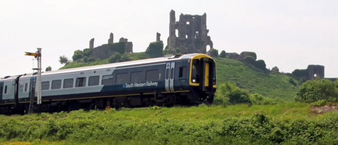
SWR Class 159 DMU Corfe Castle Saturday 26th May 2018 - PICTURE CREDIT - ANDREW PM WRIGHT

Rolling stock asset management company Porterbrook is working with South Western Railway and vehicle exhaust manufacturer Eminox to fit catalytic converters to hundreds of diesel trains across the UK’s rail network. The aim is to reduce NOx (nitrous oxide) emissions by over 80 per cent and CO (carbon monoxide) and hydrocarbons by over 90 per cent from current levels.

Well known for its smart stainless-steel exhaust systems, which can be seen on many of the large, articulated lorries that travel the motorway network on a daily basis, Eminox is a privately-owned company that was established in 1978 and has its head office and manufacturing facilities in Gainsborough, Lincolnshire.

As well as designing and manufacturing systems to reduce emissions for bus, truck, rail, marine and non-road mobile machines around the world, Eminox is a leading supplier of emission control systems for retrofit to existing vehicles. These systems include the Continuously Regenerating Trap (CRT) and SCRT®, a technology that combines CRT and Selective Catalytic Reduction (SCR) to produce a system which reduces particulate matter by both mass and number.

The trial will involve fitment of Eminox SCRT technology to a South Western Railway (SWR) Class 159 diesel multiple unit, which will be fitted with state-of-the-art telemetry to provide real-time diagnostics and performance data. The project team will then work to overcome some already-known challenges that are specific to rail applications, such as high exhaust temperature duty cycles, utilising advanced catalyst technology for the first time in a rail application.

Once it is successfully developed, this innovation is likely to be deployed on a number of existing diesel train fleets.

Eminox’s retrofit sales director Carlos Vicente said: “Eminox retrofit technology will help reduce diesel particulate matter from the rail network and deliver environmental benefits to the communities the railway serves. This is part of the government’s drive to a cleaner, greener economy by cutting emissions and removing diesel-only trains from the network by 2040.”

Porterbrook CEO Mary Grant added: “As a rolling stock asset management business, Porterbrook takes seriously its responsibility to develop innovative ways of reducing emissions. We are particularly pleased to be able to do this by drawing on proven technologies from other sectors.

“By partnering with automotive after-treatment specialists Eminox, we can accelerate the delivery of cleaner and more environmentally friendly trains to Britain’s railways.”

This project to reduce diesel emissions, which also forms part of SWR’s commitment to achieving a 56 per cent reduction in traction carbon emissions by 2023/24, is being supported by the Department for Transport’s Accelerating Innovation in Rail scheme through InnovateUK’s ‘first-of-a-kind’ funding (FoaK2).

Unipart Rail acquires Westcode operations in USA and Europe

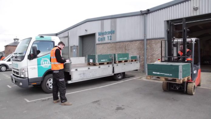
Westcode

Unipart Rail has acquired Westcode, the air supply and door systems specialist that supplies rail operators in both the Europe and North America.

The two Westcode businesses – Westcode inc and Westcode UK Limited – will continue to trade under their own brands in their respective markets. Their highly technical and skilled workforce supports an extensive range of air supply equipment with expertise ranging from the design and manufacture of reliable, cost effective compressor and air dryer packages through to the supply of pressure switches and safety valves.

In addition to the air products and HVAC (heating/ventilation/air-conditioning) design and build, Westcode has expertise and knowhow with door systems and has a comprehensive range of door system products. The Westcode UK business serves both the UK and European markets.

Noel Travers, managing director of the Unipart Rail and Manufacturing Business Divisions, said: “Unipart Rail’s acquisition of Westcode is an exciting prospect for both businesses. Westcode’s business and operating culture is an excellent fit with our current propositions and markets and the target opportunities that we are looking to develop in future. I look forward to expanding Unipart Rail’s activities in the US with the teams in place.”

Unipart Rail, a leading specialist provider of technology and supply chain solutions to the rail industry, is part of the multinational Unipart Group, with headquarters in the United Kingdom and operations in more than 100 countries.

The company already owns several other businesses including  Unipart Dorman – LED signalling and indication innovators and manufacturers, Park Signalling – signalling design and consultancy specialists, Instrumentel – remote condition monitoring specialists for high performance engines and rail applications, Key Fasteners – vending and software solutions to supply and track fasteners from the manufacturer to the train, and Samuel James Engineering – suppliers of LV switchgear and control gear systems for the Rail Industry. Now Westcode has been added to that portfolio.

Chair of Williams Rail Review speaks on the state of the industry

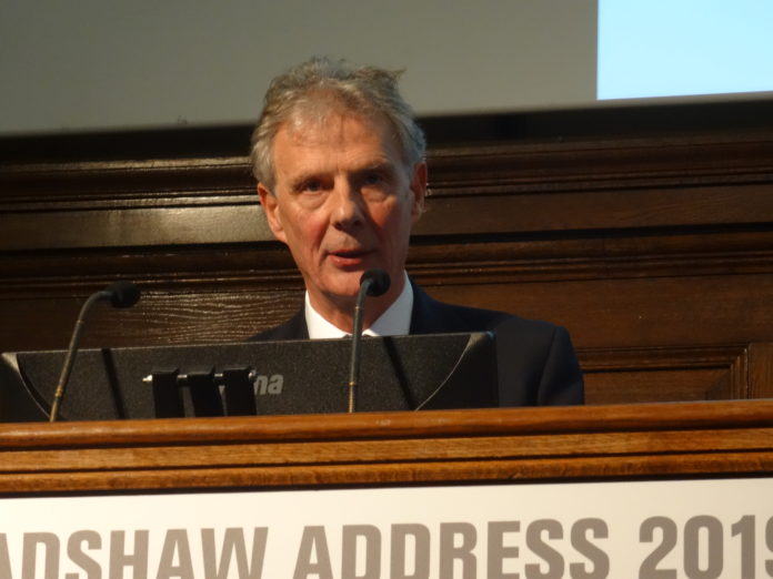
Keith Williams delivering the George Bradshaw Address 2019.

Keith Williams, the independent chair of the Williams Rail Review, delivered the 2019 Bradshaw Address at the Institution of Civil Engineers. In it, he stated that “the industry needs to fundamentally realign itself to its customers – passengers and freight. Passengers must be at the heart of the future of the railways or they will turn away”

It was, of course, difficult for him to say too much. His report isn’t due until the autumn, when his recommendations will be turned into a white paper. But he did look at how far he has got, and his views on what he has heard so far.

Readers might think that comments such as “what passengers want is a reliable service that gets them where they are going when it says it will” are a touch simplistic and obvious.  But, as Keith Williams reminded his audience, it is important to have a common understanding of the start point if the rail review is to be successful. All parties need to agree that there are symptoms which have led to the lack of public trust – then they can acknowledge that some medicine needs to be applied to bring the industry back to health.

Currently, communications are often poor, especially when things go wrong – and passengers expect better from operating companies and Network Rail. In the last few years, performance for many has gone backwards, when it should have gone forwards. Fares and ticketing are confusing. Most people want the basics sorted out.

Of course, these complaints are not exactly new, and there is already a lot of work going on within the industry to respond to them. For example, the Rail Delivery Group recently published proposals on simplifying fares structures, the Department for Transport is consulting on an extension to Pay As You Go, there are improvements coming from the Glaister review into timetabling and Andrew Haines is seeking to instil a culture of customer focus at Network Rail, having completed his 100 day review. But Keith Williams believes more is needed.

Of course, that’s why Keith has been asked to chair the Williams Review in the first place. As he said: “Whilst there have been multiple reviews over the last decade, this is the first full-blown rail review to be supported by government for some considerable time – with a very clear commitment from the Transport Secretary and from Bernadette Kelly and the whole of the department’s executive to encourage myself, the expert panel and my team to bring in root and branch change. That is the context on which we are working.”

Loss of public trust

The railway is quick to boast of its recent successes – doubling the number of passenger while running more trains than at any time in the railway’s history, all on the safest railway in Europe.

But Keith Williams commented that, despite these positives, the industry “cannot ignore some harsh realities: that poor performance, fare hikes, disruptive industrial action and the failures to deliver key infrastructure on time or to budget have contributed to a few dismal years for the railway”.

“It is a hard truth,” he added, “that, despite everything that is being done and all the money that is being spent over time, the rail industry has lost sight of its customers – passengers and freight – and therefore lost public trust.”

The review team has spent the last five months looking into the causes of this situation. They have found that there are many barriers which prevent the industry from improving and modernising its services for customers, including fragmentation and short-termism; a lack of accountability, flexibility and joined-up thinking; conflicting interests within the structure of the railway and the need for leadership throughout the system – where everyone knows their responsibilities and is held to task on performance.

Keith Williams sees his role as being to “realign the different parts of this fragmented industry so they face the same way with shared incentives, with risks (and rewards) sitting in the right places, always with a singular focus on the customer”.

Keith Williams delivering the George Bradshaw Address 2019.

A huge concern

“Many of you have told me,” he continued, “that the current rail model is no longer fit for purpose and that (while justifiably proud of what has been achieved) the industry no longer possesses the same ability or incentive to innovate at the pace at which customers expect – that what worked 20 or 25 years ago no longer works today and will not work in the future. That’s a huge concern in a fast changing world.”

Franchising is one area that he has considered. He described it as “one of the innovations of the railway since the nineteen nineties – driving growth in passengers and benefits to services”.

“But,” he continued, “with this growth, the needs of passengers have changed whilst many of the basic elements of our rail system serving those needs has not kept pace. Too often the current system incentivises short term behaviours and inhibits reform.”

His conclusion was blunt: “Franchising cannot continue in the way it is today. It is no longer delivering clear benefits for either taxpayers or farepayers.”

He was also concerned about the long-term affordability of the railway, stating: “Passengers are no longer willing to pay more when their perception of service is getting worse.”

So what can be done about it?  Keith Williams is concerned that the current system – from Network Rail, the Department for Transport and the ORR, to train operating companies and their workforce – does not have the structure and clarity of accountability it needs to properly deliver. He is a supporter of Andrew Haines’s conclusion to his 100-day review that there’s need for “radical change” at Network Rail to boost performance, to bring track and train closer together and to increase devolution, with more localised management.

During his investigation, he has discovered that there is a general frustration within the industry that rules and regulations are holding back innovation and problem solving, while the public side feels that it has to specify more and more to get the best taxpayer outcomes.

There is unlikely to be a ‘one size fits all’ solution which will work for every part of the country and all types of passenger. So Keith Williams and his team will consider all potential answers., from new models of franchising to greater public control of contracts and much more localised decision-making and integrated concessions, where those operating trains and managing infrastructure work together in genuine partnership, acting like a single business focused absolutely on customers.

But, he added, all of this needs to start happening quickly, for the sake of customers.

Repoint – New Thinking in Point Machines

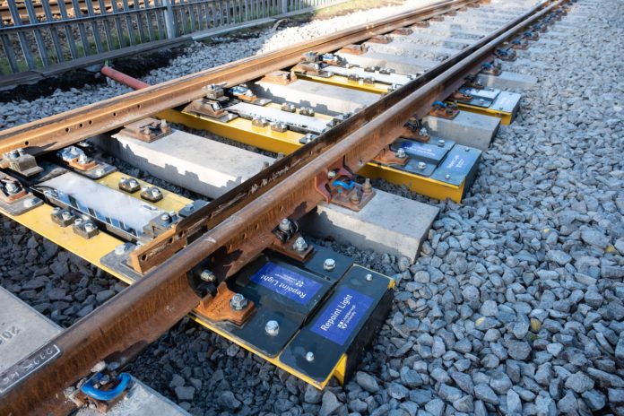
Repoint Testing at Great Central Railway.

Faults tend to have significant impact on railway performance, disrupting or stopping train movement. Railway administrators make significant efforts to reduce or eliminate sources of failures. So-called ‘single point’ failures are often the most difficult to deal with as there are no work-arounds. Examples include rails and wheelsets, which are designed to have exceptionally high integrity, an aspiration that advances in materials have supported.

Other equipment is sometimes provided with dual or even triple redundancy, so that a single fault still allows traffic to flow, provided, that is, the fault becomes evident before the other components fail! A good example is the London Underground practice of using at least two air compressors on each train.

Until now, points have been safe but subject to many single point failure modes in control, actuation, detection and locking. It was in 2010 that Professor Roger Goodall of Loughborough University, working with his then colleague Professor Roger Dixon (now with the University of Birmingham), proposed some fundamental research into track switching.

Roll forward to a very cold day in January 2019 and Professor Bob Allison, Loughborough’s Vice Chancellor, and Professor Roger Goodall, Professor of Control Engineering, welcomed some 50 guests from operators, suppliers and friends to demonstrate the results of that original research – Repoint Light – at the Great Central Railway’s Quorn and Woodhouse station.

Repoint

Repoint has been covered in Rail Engineer before (issue 131, September 2015 and issue 160, February 2018). Briefly, it seeks to eliminate single point (sorry) failure modes by employing gravity for locking and multiple actuators and detectors to achieve redundancy.

The full Repoint concept also included stub switches, but this feature was not included in the demonstrator, which, except for the actuators, is a standard size CVS flat bottom switch on concrete bearers. Indeed, it also included roller slide chairs, which are redundant in this application.

Repoint operating concept.

The switch is entirely conventional, using flat-bottom stock rails and shallow depth switch rails, and standard concrete bearers and roller base plates even though the latter have no function with these actuators. Three bearers – 1, 3 and 5 – are replaced by Repoint actuators, each one of which contains two drive motors and four Hall-effect position sensors used for detection.

The drive motors are positioned below the switch rails and are connected to cams that lift, traverse and then lower the stock rails. The motors in each bearer are synchronised electronically. The rails are not secured to the drive mechanism, which permits the rails to move if only one of the actuator pairs operates.

Each switch rail is detected in its open and closed position. Detection is arranged such that, if one rail is detected closed, the other must be detected open, and on a ‘two out of three’ voting basis based on the principles of triplicated systems used in aerospace controls. In fact, on this size switch, any one of the actuators would operate the switch and the choice of the location of the actuators was made to ensure each could raise the switch rails to clear the locking blocks of the other two.

For longer switches, the Repoint team advised that additional in-bearer actuators would be provided instead of a back-drive. As the lateral movement is twice the vertical movement (circular motion) a smaller lift would be needed to provide the appropriate lateral movement to maintain the natural line of the rails.

Repoint actuator.

The semi-circular motion of the switch rails was clearly demonstrated at the test site and showed one issue for which care will be required in set up. It is a requirement that the switch rails close firmly on the stock rails and, whilst the demonstrator switch worked, it looked feasible that the switch rail could bind on the stock rail and not drop by gravity into perfect alignment. It will be important, therefore, that the detection is only proved when the switch rail is vertically in the correct position.

This is all a matter of having the right amount of adjustment; one of the reasons for having a prototype. And the Repoint team confirmed that, indeed, the detection will not activate unless the switch rails are fully in the correct location. It would not be an issue with the full Repoint system using stub rails.

The Valley of Death

It is comparatively unusual to see such a fully engineered product developed under the leadership of an academic institution (with support from RC Designs, Baker Engineering, Progress Rail and Ramboll). The Great Central Railway trial installation represented Rail Industry Readiness Level 5, whereas it would be more usual to stop at RIRL 3.

Loughborough deliberately sought to try and overcome the so-called “valley of death”, where innovations stall through lack of investors to get them into production, and to recognise that, in general, Network Rail expects new products to be at least at RIRL 6 before they can be considered for trail on the ‘big’ railway.

It was good to see that the demonstration at Quorn was attended by many potential industrial partners.

Economics

Your writer has been involved with the development of point machines before, and it is quite conceivable that a seven-digit sum can be spent developing and proving new actuators before any see more than prototype service. Unless an actuator is adopted internationally, amortising this cost can be a significant issue.

Equally, having three actuators rather than one might increase costs, albeit, the Repoint Light actuator looks less complicated than many other designs. That said, in the context of the overall cost of installing a switch, the cost of the actuators is small. However, in conversation with one of the potential industrial partners, it became apparent that the conditions of the research grants make it difficult for any one supplier to adopt Repoint exclusively.

So it was good that many former colleagues, experienced in introducing new switch mechanisms, were impressed with the concept and its presentation. They were seeing potential issues and how they might be addressed, but the prize of being able to keep a switch in service to the end of traffic, even if a component fails, is one worth working for.

Great Central Railway themselves were excellent hosts, including a Hall class locomotive, complete with a Repoint train headboard, providing an excellent trip for all the guests.

Thanks to Loughborough University’s Professor Roger Goodall and Dr Tim Harrison for their assistance in completing this article. More information can be found at www.lboro.ac.uk/enterprise/repoint/

Train detection

One of the main safety requirements of a train control system is that, before a train is given authority to move along a section of line, it has to be proved to be clear of other traffic. Thus, the ability to detect the presence of a train on a particular stretch of track is a key enabler for automatic signalling, and hence modern train control.

There are two types of technology generally used for train detection, a track circuit or an axle counter.

The track circuit continuously proves the absence of a train from a given section of track in a fail-safe manner. It cannot absolutely prove the presence of a train, since any failure mode will give the same indication as if a train is present, but, by proving the absence of a train, a clear track circuit can be used to confirm that it is safe to set a route and permit a train to proceed.

As its name suggests, with an axle counter system track mounted equipment counts axles entering and leaving a track section at each of its extremities. This information is evaluated to determine whether the track section is occupied or clear.

Fundamental design principles

With a track circuit system, a section of railway track is normally electrically defined by the provision of insulated rail joints (IRJ) in the rails. A source of electrical energy is connected, via a series impedance or resistance, across the rails at one end, and a detector is connected across the rails at the other end.

If there is no train within its boundaries, the detector senses the transmitted electrical energy and energises a repeater circuit. This conveys the absence of a train to the signalling system (track circuit clear). The metal axles of a train within the track circuit will cause the rails to be ‘short circuited’ such that the detector no longer sees sufficient electrical energy and it changes state, informing the signalling system (track circuit occupied).

Any electrical short-circuit between the rails, whether caused by a train or not, or any disconnection within the circuit (for example a cable being cut or falling off the rail), will ‘fail’ the track circuit and inform the signalling system that the track circuit is occupied. This means that any fault will cause the system to ‘fail safe’ – a good thing. However, it can also lead to spurious results and unreliability if the track circuit is not maintained or set up correctly. How many times have we heard the announcement “Trains delayed due to a track circuit failure”?

Correct operation of a track circuit also depends upon good electrical contact between a train’s wheels and the rails, together with a continuous low-impedance path between each wheel via the connecting axle on the train.

DC, AC and coded track circuits

Simple as the track circuit may seem – detecting a train is just a question of monitoring a short circuit between the rails – there are various ways of powering and controlling the system, and all have their benefits and weaknesses.

The source of electrical energy may be DC, AC at power frequencies (typically 50Hz), AC at audio frequencies (several thousand Hz) or a series of impulses or complex waveforms as used by coded track circuits. Similarly, the detector may be a simple relay, a simple AC ‘vane’ relay or a more complex receiver tuned to a particular frequency or pattern of signals.

On electrified railways, the track-circuit equipment must also work despite the large return currents passing through the rails from the electric traction systems. Some track circuits, therefore, have to be either AC or DC traction immune, or, in some parts of the network, both at once.

In addition, the two rails on a railway are not perfectly insulated from each other. There is always a leakage path between the two through the rail fixings, the sleepers, the ballast and the ground itself. This is called the ballast resistance. Its value is dependent upon the condition of any insulation, the cleanliness of the ballast, and the prevailing weather conditions. It is inversely proportional to track circuit length, with lower values in wet conditions where there is bad drainage and/or contamination from conductive materials. In simple terms, if the track is flooded, the track circuit will show occupied and the signal controlling the section will remain red.

Wet tunnels can be a particular problem, as the conditions can vary quite significantly, and higher values (the lower the resistance the worse the problem, the better the insulation the higher the resistance) may be obtained in dry/clean conditions or during frosty weather. A reliable track circuit must therefore be able to operate over a wide variation of ballast resistance.

One difficulty with adjusting track circuits is knowing the prevailing value of ballast resistance. If a track circuit fails due to wet weather, it may be possible to remedy the situation by reducing the feed resistance. But it is important that the track circuit is re-tested after it has dried out, otherwise a ‘wrong side failure’ may occur with trains not being detected.

This adjustment and testing has to be carried out manually, putting staff out on the railway and, therefore, at risk.

Rust films and contaminants

The resistance through the train’s wheels and axles is also important, as it is the train which shorts out the track circuit. The presence of a light rust film on the rail head and/or wheel results in a high resistance which may prevent the short circuit, and therefore the train detection, from occurring. Very heavy rust films, from prolonged disuse, can result in many track circuits being incapable of detecting trains, especially lightweight trains as they are not heavy enough to penetrate the layer of rust.

The mechanical strength of light rust films is much reduced by the presence of moisture, when the contaminant tends to be squeezed out from the wheel/rail contact patch. Therefore, lightly rusted rails will only be a problem when dry.

This problem is most severe when conditions combine showers with a drying wind, or after prolonged periods without trains. Care needs to be taken after track relaying, when track circuits must not be restored to full operation until a reasonable surface has been created.

Other contaminants that increase the electrical resistance between the rails and the train’s wheels can cause the same problems. Those associated with falling leaves are generally limited to autumn and confined to particular locations, although even some built-up areas can be affected. Leaves are drawn into the wheel-rail interface by the passage of a train where they are squashed into a pulp. This contaminates both the rail and wheel, causing wheel-slip problems as well as reducing electrical conductivity.

In simple terms, reasonably dry weather with little wind will cause the leaves to fall gradually over a long time period and to be reasonably sap-free when they do fall. But gale conditions will lead to a sudden fall of sap-laden leaves, giving rise to the worst conditions.

Problems with coal dust on the rail head tend to be confined to colliery areas, and so this is not the problem it once was. Sand contamination is not so much due to the seaside but is usually associated with slow-moving locomotives using sanders excessively. In each case, the effect is similar to heavy rust.

Problems can also occur with ballast condition issues associated with carbon-based contaminants, and of course heavy rain causing puddles and floods can short out the track circuits completely.

Train issues

Where a thin film of contaminant insulates the wheel from the rail, this can often be pierced by a rough surface. The older style of tread brakes caused the tyres to be roughened at each brake application, whereas more modern disc-braked trains allow the tyres to be rolled into a very smooth surface condition. Therefore, older tread-braked trains provided better track circuit operation than modern disc-braked trains.

Similarly, the axle weight has an effect, as a heavy load will pierce a film more easily. Again, modern lightweight trains (and not-so modern ones, such as Pacers), designed to keep track wear down to a minimum, have more problems than old-style heavy freight trains.

One positive result from today’s crowded railway, however, is that busy lines have little chance to rust, reducing the problem. However, seldom-used branch lines, particularly those in coastal regions, are particularly at risk.

To assist vehicles to shunt track circuits, a device known as the ‘Track Circuit Assister’ (TCA) is fitted to modern trains to induce an electrical potential between the wheelset and the rail head. Typically, a TCA consists of a control unit and aerial with associated tuning unit, mounted between a pair of wheelsets close to the rails.

Bombardier EBITrack400 track receiver.

Insulation

As has been described, any direct metallic connection between the two rails will be interpreted as a train and will cause the track circuit to fail occupied. Therefore, apart from the insulated rail joints used to electrically separate sections of rail, the reliable operation of track circuits requires the provision of other insulators.

At a set of points, for example, there are many of these cross-rail connections – stretcher bars, point motors and heating elements – all of which need to be fitted with insulators, giving rise to quite complex insulator and bonding arrangements.

Damp concrete or wooden sleepers can behave as an electrochemical secondary cell, which can give rise to residual voltage problems with DC track circuits.

Concrete sleepers incorporate a rubber pad under the rail foot and moulded insulations where the fixings bear on the top of the foot. These increase ballast resistance to levels significantly higher than those obtained with timber sleepers. However, the insulations can erode due to the vibration of passing traffic and, consequently, require inspection and periodical replacement – another maintenance headache.

Obviously, steel sleepers are even more of a potential hazard. They are also insulated, but any degradation of that insulation will result in severe problems.

Bonding

Bonding is the means by which the individual components of the railway track are connected together electrically for track circuit purposes. The term also includes the additional electrical connections necessary for the proper operation of electric traction. In order for a track circuit to fail safe (to show occupied) in the event of a bonding disconnection, it is necessary to bond all elements of the track circuit in series, so that any one failure breaks the circuit.

Insulated rail joints can be expensive, both to install and to maintain, especially on tracks subjected to high speed, high axle-weight traffic or where there is an intensive service. Also, in areas of switches and crossings, it may not be physically possible to arrange total series-bonding of both rails.

One solution is the use of audio-frequency AC track circuits which permits the physical limits of an individual track circuit to be defined by ‘tuned’ short circuits between the rails, rather than by insulators in the rails. The track circuits operate at different audio frequencies and each tuning unit is designed to its own track frequency. It is possible, with careful design, to arrange a short overlap in the centre of the tuned zone where both track circuits are effectively shunted.

However, it is not always an ideal solution for complex switching and crossing layouts and, because of the additional complication of significant rail impedance with parallel bonding, audio-frequency track circuits are often unsuitable unless the layout is quite simple.

Track circuits and electric traction

Track circuit arrangements in electrified areas are constrained by the need to ensure safe and reliable operation of both signalling and traction systems. This means that the track circuit must be immune to both false operation and damage by the flow of traction currents through the rails.

It also causes complications because, while the signalling track circuit is broken up into sections by insulated rail joints, the traction current return needs a continuous electrical connection back to the substation.

This explains the need for impedance bonds. These are devices that present a low-impedance to traction current and a higher impedance to track circuit current. In simple terms, they allow traction current to pass along the rail, but stop track circuit current in order to create track circuit sections.

Although track circuits will normally be inherently immune to false operation (wrong side failure) from the presence of traction currents flowing in the rails, any imbalance can create a signal that looks like a track circuit feed. The traction currents can also be of a magnitude sufficient to cause damage to equipment, or a right-side failure of the track circuit.

In DC-electrified areas, the relatively low supply voltage results in high currents returning to the sub-stations via the running rails. In order to minimise voltage drop in the DC-traction supply, all running rails are used for the return of traction currents wherever possible, and therefore double-rail track circuits are used.

In switches and crossings, however, it is not usually possible to bond the track in double-rail form, therefore single-rail track circuits have to be installed. Traditionally, in DC-electrified areas, the track circuits were all AC, using phase-sensitive vane relays, so they could be distinguished from the underlying DC. Nowadays, jointless modulated audio-frequency track circuits are used, reducing the number of insulated rail joints and impedance bonds required in plain-line DC areas.

In 25kV AC electrified areas, traction currents are generally lower than in DC systems and, in most cases, single rail traction return is sufficient for electrification purposes. However, on occasion, increased traffic levels and alternative feeding arrangements may increase the need for both running rails to be used for traction return.

Once again, all track circuits in AC electrified areas were traditionally operated with DC current, although feed and relay components were specifically modified to provide protection from damage and immunity to interference.

In combined AC and DC traction current areas, the choice of track circuits has to be limited to those that are immune to both and do not use frequencies (including harmonics) contained in the traction supply. With the variable voltage and frequency traction packages on modern trains, there can be pretty much any frequency in the rail (or close to it). Together with traction pack and power supply failure modes, the harmonic issues can get extremely complicated.

Modern traction units employing active control methods (such as three-phase drives) can actively generate currents at other frequencies and superimpose them onto the supply. This problem can be designed out, but it’s not easy to avoid critical frequencies and some interference is possible.

Axle counters

In many countries of the world, modern axle counting systems have long since taken over from track circuits, as axle counters suffer from none of the above issues. For example, rails can be under water and trains can still run. Axle counters are now the preferred method of train detection for all new schemes in Great Britain, with systems supplied by both Thales and Frauscher.

One particular advantage of axle counters over track circuits is that they can be overlaid on another detection system (whether track circuits or another axle counter system) for upgrade purposes – whereas usually only one-track circuit can be installed on a section of rail at a time.

Inside a Thales axle counter.

Axle counters are not without their problems, however. An axle-counter section cannot be made ‘occupied’ by the use of a track-circuit operating clip to protect a train, nor will an axle-counter system detect a broken rail (although a track circuit will also not detect all broken rails, especially in single-rail track-circuit areas).

When an axle-counter system fails, for example due to a power supply problem, it loses track of how many axles have passed through it. Therefore, for safety, it will always recover and ‘come back on line’ showing the section of line occupied. The section then needs to be proved clear of a train before the axle counters can be restored and reset, which can take some time.

The introduction of GSM-R for emergency communications has provided an acceptable replacement for the non-use of track circuit operating clips.

Signalling engineers were always nervous of track circuits being relied on for detecting broken rails as they were never designed for this purpose. Improved rail integrity and ultrasonic testing has provided a far better method of detecting rail problems and the number of broken rails across the network has reduced dramatically.

Another problem with axle counters is that a right-side failure can occur when a wheel stops directly above the axle counter inductive sensor, known as ‘wheel rock’. The previous section will remain occupied with no train present and the time-consuming process of reset and restore has to be carried out. That can cause difficulties at a busy station, where the problem can also occur for multiple short trains stopped along the same platform. For these reasons, Thameslink has elected to retain track circuits on the core section where there are multiple split sections along the platforms.

Remote condition monitoring

Track circuits will still be used for many years to come, such is the huge job in resignalling the network, so clever asset management and maintenance techniques will be required. One initiative that has helped reliability is remote condition monitoring (RCM). By monitoring the track circuit current, potential failure modes can be predicted and interventions planned before failure. It is not something that is easy to automate, but there have been improvements in track circuit reliability with potentially more to come.

One recent innovation on London’s Victoria line is RCM that allows the new jointless track circuits to be inspected in real time from remote locations, improving reliability. Prior to its implementation, track circuits had to be checked by hand using digital multi-meters, which was a time-consuming task and not conducive to finding faults before they occurred. The new RCM is anticipated to reduce the lost customer hours by 39,000 per annum.

A similar scheme is being implemented in Singapore, but built into the jointless track circuit baseplates to provide even greater asset information.

On the other hand, axle-counter systems also have sophisticated built-in remote diagnostics and this is one example of the digital railway delivering results today.

Both methods of train detection, track circuits and axle counters, have their supporters and detractors. However, for now, the world seems to be moving in the direction of axle counters, that is, until something else comes along. 

Thanks to Mark Glover, head of innovation, Siemens Rail Automation UK, for his assistance with this article.

NOKIA: the common bearer

A common bearer (transport layer) telecoms network takes advantage of the new digital technologies and ‘big data’ applications in order to provide a safe, efficient, reliable railway. In very simple terms, this unseen telecoms network is the ‘glue’ that binds the digital railway together and is therefore hugely important. It will be the heart and veins of the digital railway.

Railways need to modernise and to provide improved capacity and on-time services, especially as the competition from autonomous vehicles is gaining ground all of the time. Reliable, efficient and high-capacity connectivity is essential in order for railways to make efficiencies, innovate and compete. There’s also a growing desire and need to improve mobile connectivity for both passengers and operational services.

Use cases

There are potentially a lot of use cases to support along the rail corridor. These include operational voice and data services for train control, SCADA for electrification control, remote condition monitoring, CCTV, CIS, GSM-R, IoT, business voice and data, third-party commercial fibre connectivity and broadband track-to-train connectivity.

The digitalisation of the rail network means finally bringing all of these services together on a cost effective, reliable and resilient fibre network that delivers not only on security, with the potential to create virtual private networks (VPN), but also on an ability to expand over a 30-year period.

In some railways, the data services today run across disparate, ageing networks which can be costly to manage and, invariably, fail from time to time. The networks can be near impossible to correlate together and require significant resources to ensure safe, reliable operation. Aging infrastructure (copper, fibre, transmission equipment) can lead to common problems around manageability, to a high cost to maintain and upgrade, and in some cases to operational failures that can lead to train delays.

Globally, many railway infrastructure managers and railway undertakings currently use the interoperable radio communications network, GSM-R (Global System for Mobile Communications – Rail), for operational voice communications and to provide the data bearer for ETCS (European Train Control System). In the European Union this is legally mandated in the Technical Specifications for Interoperability that are applicable in the European Member States. Voice and data communications are also used for various other applications.

GSM-R has been a huge success all over the world, not just Europe, but it is a MOTS (modified off-the-shelf technology) system based around manufacturers’ commercial GSM offerings, enhanced to deliver specific ‘R’ (railway) functionality. Due to the product modifications required to provide this functionality, and the need to utilise a non-commercial radio spectrum, much of the equipment utilised for GSM-R comprises manufacturers’ special-build equipment and/or software variants. The use of MOTS technology for GSM-R has proven expensive for the railways, both interms of capital and operational expenditure.

The predicted obsolescence of GSM-R by 2030, combined with the long-term life expectancy of ETCS (2050) and the railway’s business needs, have led to identifying a successor for GSM-R. This will have to be future proof, learn from past experiences/lessons and comply with railway requirements.

The successor is the Future Railways Mobile Communication System (FRMCS). This is envisaged to provide the same services, plus a higher data speed capability for operational and business purposes (including real time video), with the option of providing passenger mobile connections. Some metro networks are also interested in FRMCS, not just the main-line railways. All this will require each railway to have a reliable, high-bandwidth common bearer.

Every GSM-R or FRMCS failure for ETCS will shut the railway just as surely as a track circuit failure would; so high availability is essential. CBTC systems for metros are also reliant on some form of radio connection. While the future of train control in both ETCS and CBTC will be radio-connection based, radio will only provide the last few kilometres of connectivity, and the majority of the connection path will still be via fixed telecommunications using fibre, routers and switches with a common bearer.

Passenger bandwidth requirements

Mobile coverage and Wi-Fi are increasingly considered as the essential ‘4th utility’, similar to water, gas and electricity, and rail passengers now expect a reliable and seamless service. The government’s current proposals are to provide for ‘uninterrupted’ Wi-Fi and Mobile (5G) broadband speeds of up to 1Gbps on-board all UK mainline train routes by 2025. This is supported by the communications regulator Ofcom, which has set out its vision for the data connectivity that will be required by 2025 on British trains. From its research, Ofcom says that, in seven years’ time, a crowded commuter train is likely to need 3.6Gbps of mobile data capacity to meet the connectivity needs of its passengers.

A report by Kinetic and Exterion into the spending habits of commuters estimates that, across the whole UK, country commuters apparently spend an average of £89 per week using their mobile devices, with London commuters spending £153 per week. The report says that, in total, commuters spend an astonishing £23 billion per year via their mobile devices while on the move. So, the bandwidth demand is there and growing, but how can it be delivered?

The required track-to-train connectivity will involve many different considerations, such as determining the business model on which such a service would be run, how the deployment would be funded, and potential interoperability across multiple routes or TOCs. The UK rail network is a complex one, with lots of stakeholders – Network Rail, train operators, rolling stock providers and mobile networks – so making the change to deliver the required connectivity requires a high level of co-operation. But, at its heart, a high-bandwidth fixed trackside data service bearer will be required, irrespective of whether the radio system is FRMCS or relies on public mobile network operators, as of today.

FRMCS is likely to be based on a private or shared LTE/5G platform and telecommunications specialist Nokia has already successfully deployed private LTE networks in other transport industries, including networks to control autonomous vehicles and freight shipping ports. It is also one of leading players in the development and deployment of the next generation of 5G radio networks all over the world.

Telecoms network requirements

To support a modern railway with its data requirements and truly drive productivity gains, the telecoms network must be fundamentally more. It must be:

Accessible: Networks must provide deeper reach and extend everywhere there is a business or operational requirement. Regardless of access medium, dedicated network connectivity is a must. Various wireless, fixed, IP, optical and microwave technologies must work together to ensure that no site, signalling controller, sensor, worker or customer is left behind and they are all provided with the right priority of service.

Elastic: Networks must be dynamic and programmable. As new control and command digital signalling is rolled out, and as new sites are added and demands fluctuate, the network should adjust in an automated fashion to optimise resource utilisation and meet application needs in accordance with the railway’s requirements. The signalling supplier will require access to the telecoms data network in order for him to safely test the overall train signalling system. This may also require the telecom node to share the domestic mains electric supply with the signalling system, with no outage to either the signalling or telecoms equipment. Dynamically optimised connectivity should be established wherever it is needed. Programmatic handling of changes in the connections to (and between) local, edge and hybrid clouds will be essential to the performance of the applications and the viability of key use cases.

High-performance: The network should deliver seamless, deterministic performance across all the applications it supports. While the requirements of each set of applications may vary, performance against stringent guidelines must be independently guaranteed and demonstrated for each application.

Resilient: For applications critical to both business and railway operations, downtime can have catastrophic consequences. Networks must ensure availability at all costs to deliver safety and meet business objectives, with 99.9999 per cent uptime a requirement. That last decimal place is important – 99.999 per cent reliability brings about five minutes downtime per year, with 99.9999 per cent – it’s only 30 seconds. Train delay costs and reputations are at risk and, in some cases, human lives and safety may also be at stake.

Secure: As business perimeters expand and devices proliferate, so does the threat radius. Railways know they are at risk from cyber-attacks and cyber security is an essential part of every safety-case approval. Data networks should be a part of the enterprise security solution, rather than the problem. A smart network fabric can play a role in minimising certain threats and ensure that changes are in strict accordance with enterprise policy.

Scalable: Richer data provides deeper context and higher value. A simple move to video for surveillance or for scene analytics necessitates higher bandwidth at each site. Critical real-time video images are considered to be an effective mitigation measure in relation to hazards that may not be detected otherwise by the train control system. In addition, real time video images can enhance operational performance of the railway system when used to support the end user within the target environment. For example, a video application could be used for automatic train operation (ATO), automated detection of objects on or near tracks in the context of autonomous train operation, supervision of platform and tunnels (either by a remote human user or in an automated way) and monitor the situation in the event of an alarm (supervision of railway track, doors, train, smoke detection). It could also be used to transfer a video image in parallel with voice communication (for example, during Railway Emergency Communication). The FRMCS functional working group has just signed off User Requirements Specification (URS) 4.0.0, which includes real time video as a service for the next generation of train radio, so higher fixed bandwidth for video will be an operational requirement.

Each additional use will require the deployment of additional computational power. Control of automated vehicles, for example, may ultimately require the processing and coordination of data from a wide spectrum of sources, including surveillance cameras, in-vehicle sensors and other devices.

The use of high-fidelity information from a range of sensors will improve automation decisions made across a wide spectrum of industrials. As a result, business-critical infrastructure must operate and grow for periods of a decade or longer.

Networks should be designed in a manner that anticipates and adapts to expansion of bandwidth, processing and other capabilities. Within the duration of the life of the telecoms network there will undoubtedly be many compelling new applications that are unknown today, all of which will require higher bandwidth.

Transport layer

Fundamentally, it is an optical-to-the-edge architecture that would use DWM (dense wavelength division multiplex) technology to deliver very tight services from an operations and maintenance perspective (fibre break detection and location, lambda performance, fibre degradation and prediction). All railway services will be separate (on their own lambda, or optical channel) with full resilience. Each lambda can support (on Nokia silicon) up to 400Gbps and, with over 96 lambdas per fibre pair, one can see how this will scale!

Nokia has addressed the problem by introducing a common bearer (transport layer) in multiple-use cases. This addresses both legacy problems and the safety requirements for fibre-based sub-access connectivity, together with the growth and low latency characteristics required by LTE/5G transport, which will form the basis of the next generation of train radio system. The solution provides the opportunity to bring all of the data networks together whilst both maintaining security and separacy and also providing for the possibility of huge expansion over a 30-year timeline.

Some major rail operators are already embracing FTTE (fibre to the edge) to great effect. One example is Schweizerische Bundesbahnen (SBB – Swiss National Railways), which is moving to a fibre underlay with IP/MPLS overlay, to be delivered, managed and operated by Nokia.

SBB, Switzerland’s largest transportation operator that moves both passengers and freight throughout the country, is upgrading its 8,100km communications network of transmission cables and more than 8,500 components to an advanced, converged communications network by 2020.

SBBs synchronous digital hierarchy (SDH) operational communications network has supported all mission-critical applications, including CCTV, train control, signalling and GSM-R while a separate business IT LAN, similar to the Network Rail Fixed Telecom Network (FTN), has handled non-vital services. SBB seeks to realise efficiencies by upgrading and rationalising the technologies used for both networks and to gain flexibility in the deployment of new services, such as passenger connectivity, as well as advanced applications for growth.

Targeted to be fully operational in 2020, the new nationwide data network will consist of more than 10,000 active elements at over 1,300 sites adjacent to the railway and at approximately 500 offices.

SBB’s existing SDH infrastructure and separate IP platform will be migrated to an integrated IP/MPLS and optical network. An innovative architecture will address all of SBB’s needs and support a future-proof networking solution. This encompasses a fully redundant fibre-optic communications wavelength division multiplex (WDM) transport layer that will carry data from different sources. Two different IP/MPLS networks will run on top: one full redundant network for all mission-critical applications, including train control and signalling, GSM-R, interlocking and other applications; and another for services and applications such as CIS, ultra-broadband passenger connectivity, ticketing and a LAN/WLAN for SBB employees.

Nokia service routers and service aggregation routers, with end-to-end network management provided by Nokia Service Aware Manager, will also be deployed.

The SBB network utilises the same Nokia common-bearer architecture outlined in this article – so if other railways were to adopt similar, they would not be in uncharted territory and therefore would be able to deploy the heart and veins of the digital railway with minimal risk.