Home Blog Page 123

Seven into Four does go – at Thickley Wood footbridge

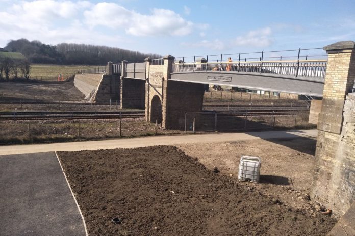
The refurbished main span of Thickley Wood bridge.

Thickley Wood footbridge at Shildon, County Durham, is unusual but reflects the growth and decline of the local coalfields. Spanning the historic Stockton & Darlington Railway, this bridge dates from 1857, at which time it was a cast iron span of 16.5 metres over the Darlington to Bishop Auckland line.

As the collieries expanded to meet the demands of Victorian Britain’s industries, so were additional sidings required. In 1868, a second wrought iron girder span of 10.9 metres was added to the south and, in 1875, four additional wrought iron lattice spans, one of 7.7 metres and three of 15.2 metres, were added to the south. At this time there were two running lines and six sidings passing below the bridge.

Although, there had been 27 miles of sidings around Shildon at their peak, by 2018, there were just two running lines and a single siding passing beneath the bridge, with the first three spans being redundant.

The sidings at Shildon in their heyday, with Thickley Wood bridge in the background.

The bridge carries a footpath, much used by walkers and recreational visitors to Thickley Wood. The bridge is just 40 metres to the east of ‘Locomotion’, part of the National Railway Museum.

The oldest section, ‘span 7’, is cast iron and is listed Grade II because it is “a single casting of exceptional length”. This includes a maker’s plate, ‘HARRIS MDCCCLVII MAKER’. John Harris was the Stockton & Darlington Railway’s resident engineer from 1836 to 1844. He then became self-employed, and one of his many businesses was Hopetown foundry, in Darlington, where he cast this bridge.

It was recognised by Network Rail that parts of the bridge were in very poor condition and that substantial investment would be required to return it to full strength.

Seen in 2017, the bridge’s poor condition contrasts with the modern Locomotion museum alongside.

Local concerns

The 1825 Stockton & Darlington Railway was the birthplace of Britain’s railway system and was designated in 2018 by Historic England as a Heritage Action Zone. This is part of a five-year project to unlock potential investment into the structures and environment surrounding the Stockton & Darlington Railway with the aim of creating an iconic tourist attraction that will increase economic growth in the surrounding area. As a result, any works around it have the potential to be controversial.

In 2018 Network Rail submitted an application for local authority planning consent for the works as they would affect a listed structure. This described the removal of the redundant spans replacing these with an embankment and the refurbishment of the remaining spans. This being the only realistic economic solution.

These proposals met with much criticism locally. There were concerns that the work would destroy the character of the bridge and the wish was expressed that the bridge should be preserved especially leading up to the bicentenary of the S&DR.

Thickley Wood bridge, before renovation (top) and after (bottom).

Jonny Ham, Network Rail’s project manager, explained: “The design stage was a real challenge and we treated the whole bridge as a listed structure, even though it was only the original three spans that were protected.

“We were conscious that we wanted to be sympathetic to the design of the bridge, so we replicated the original metal latticework in the railings of the new ramped access, and painted the bridge in its original shade of grey”.

In its submission, Network Rail commented: “By maintaining different styles of bridge across the spans, the appearance of the bridge will alter, but this will tell a story of the development of the railway across a period of time. The appearance of the bridge will reflect one altered over the years to accommodate an ever-changing railway and local landscape.”

In March 2018, both Shildon Town Council and Durham County Council considered the application and raised no objections to Network Rail’s proposals.

Design

Leeds-based Construction Marine Ltd (CML) was awarded the £1.6 million contract for the works under its RCDP (Renewals Collaborative Delivery Programme) framework contract. The project at this point was at GRIP 3 (option selection) stage. CML’s Nigel Lea and Mark Anderson explained to Rail Engineer how the project was delivered.

CML prepared an options report, based on Network Rail’s remit, with several alternatives being considered for each of the bridge’s seven spans. Network Rail had liaised over a couple of years with Durham County Council to understand which options were likely to be acceptable at this sensitive location, and this guided the optioneering process.

CML prepared an options report, based on Network Rail’s remit, with several alternatives being considered for each of the bridge’s seven spans. Network Rail had liaised over a couple of years with Durham County Council to understand which options were likely to be acceptable at this sensitive location, and this guided the optioneering process.

Span 4, spanning the Locomotion access siding and overgrown siding area, before work began.

There was prolonged and more detailed consideration on costing and practicality of the various options than is usual, to ensure that the planning application would be very detailed, and the logic fully justified.

The agreed solutions were:

  • The four redundant 1875 lattice side-spans (1-4) would be removed and spans 1 to 3 replaced with an embankment. This was designed to be a reinforced earth structure, reducing fill requirements but also enabling its footprint to remain much the same as the original bridge, and fit within the adjacent boundary fencing of the ‘Locomotion’ museum;
  • Span 4 would be replaced with a standard LM footbridge welded steel span. The original pier between spans 3 and 4 was to become an abutment, with new wing walls built from masonry recovered from the demolished piers. The reinforced embankment behind the abutment would be self-supporting but a compressible layer between fill and masonry would be provided to ensure that no thrust would be imposed on the slender pier;
  • Span 5 (1868 span) would be retained and the wrought iron structure repaired and repainted, timber decking refurbished and full height parapet handrails installed;
  • Span 6 would receive minor masonry repairs and have a lightweight in-situ concrete deck installed;
  • Span 7 (the listed 1857 cast iron span), would have stitch repairs to its cast iron cross girders, making good poor historic repairs, and would be repainted. This, too, would have a lightweight concrete deck over the waterproofed jack arches, and improved parapets;
  • In addition, a second embankment would be formed to provide a wheelchair-friendly access ramp up to span 7 from the former track bed, connecting with the foot and cycleway that connects the town to the museum. This was to be funded by Durham County Council and was designed to be easily removable as it occupies a former track bed that might at some point in the future be required should freight expansion take place.

Construction

Before works began at the end of August 2018, the CML project team met with representatives of Network Rail, National Railway Museum, landowners and Friends of the Stockton & Darlington Railway, to fully explain the scope and timeline of the project.

Removing the old Span 3, September 2018.

Following initial site clearance operations, the team installed a temporary 120-metre access road from the site compound, which was established adjacent to the ‘Locomotion’ access road. This was designed to cope with the bulk earthworks deliveries and bridge delivery. Good, regular liaison with the museum team ensured deliveries of plant and materials did not affect their peak visitor periods. Crane pads and a large laydown area were constructed to store the removed and new spans.

The siding into ‘Locomotion’ through span 4, was blocked throughout the project.

On 15/16 September, the four lattice spans were lifted out by a 150-tonne LTM 1150 Crane. The 10-tonne spans 1 and 2 were lifted out during the day and these placed in the laydown area. The crane then de-rigged and moved forward to lift out spans 3 and 4 during a 23:00-06:00 possession of the Darlington – Bishop Auckland line.

During November to January, the new reinforced earth embankment was designed and constructed by Maccaferri using its Terramesh system. This combined the use of galvanised steel cages to face the embankment with geo-fabric tensile straps installed in layers as the embankment was constructed.

The fill for the embankment facing was locally sourced gabion stone, tipped adjacent to the work areas and loaded into the 3000mm wide facing baskets, to create a drystone wall appearance. The central fill was placed by 25-tonne and 13-tonne excavators, a D6 bulldozer and dumptrucks and compacted in 150mm layers by rollers and plates.

Forming the base of the new southern embankment with Paragrid 80/50 reinforcement.

The geotextile straps were installed in sequence with the erection of the facing baskets. Paragrid 80/05 reinforcement was laid every other layer at the face edge. As the works proceeded, temporary scaffold edge protection was attached to the baskets.

Pockets of pre-seeded soil mixture were incorporated into the upper section of the face, which will result in grass-covered walls. The lower will remain stone-faced, matching the adjacent walls of ‘Locomotion’. The new access ramp at the north end was constructed using a mix of reinforced earth and, at the lower ends, natural fill. The steel footway fencing of the south embankment incorporates a lattice design, reflecting the original girders, the north ramp has steel, five-rail estate fencing.

The masonry wing walls and repairs to other part of the structure were carried out by a team from Darlington-based D France Masonry. They constructed the walls using recovered stone from the demolished piers, matching exactly the historic masonry.            

The new span 4 was fabricated by Britcon Engineering Services at Scunthorpe and the pre-cast retention units by Ebor Concrete. These were installed in possession by a Liebherr 160-tonne crane – the bridge unit weighed 9 tonnes and this planned lift was delayed by two weeks due to high winds.

The repairs to span 5 were carried out by HS Carlsteel Engineering. This span has a timber deck, which was refurbished using timbers recovered from the demolished spans 1-4.

Spans 5 and 7 were wet blasted to Sa2.5, and an M24 paint system applied by Bagnalls, in a series of Saturday and weeknight rules of the route possessions of the Darlington – Bishop Auckland line.

Following the blasting, further cracking was identified in the bottom flange of the cast main beams. A supplementary planning consent for additional repairs to the listed structure was quickly agreed. These fractures, together with the known problems with the cross girders, were repaired using the Metalock stitch system.

The heritage of the site and structure were very much in the CML teams mind during the project. In addition to the use of recovered timber and masonry, the redundant lattice span 4 was donated to the Friends of the Stockton & Darlington Railway. Ross Chisholm explained that this is in store at the Weardale Railway but that they hope to use this as a training project for the next generation of tradespeople. Once restored it will be displayed within the Heritage Action Zone.

The opening of the completed bridge took place on 28 March, attended by 30 representatives from stakeholding groups. Despite their initial concerns at the scope of the works, the Friends of the Stockton & Darlington Railway complimented Network Rail and CML, describing the bridge as a “good job well done” and were very pleased to have been involved in the project.

Striving for Innovation: An industry challenge

Creative thinking ideas brain innovation concept. Light bulb on yellow background

Signal engineers tend to have a measure of distrust when new ideas and concepts are put forward. This is understandable, given that any radical change to signalling practices can have catastrophic consequences if it all goes wrong and accidents occur.

It has taken over 20 years to develop and prove ERTMS/ETCS but, even now, the ultimate goal of Level 3 systems with no lineside signals and radio-based train detection seems many years away.

Nonetheless, progress has to be made with technology and engineering methods in order to drive down the cost of signalling, now measured by the terminology SEUs (Signalling Equivalent Units), a measurement based on the number of items controlled by the central interlocking.

Network Rail has had a Signalling Innovations Group (SIG) for a number of years and it holds a seminar annually to enlighten the railway community on the initiatives it is engaged in. Rail Engineer has reported on this event in the past, the last time being in 2014, so it was high time to take a re-look at what the group is currently engaged in and a meeting with the Group’s head, David Shipman, was held recently.

Group organisation and mission

Having national implications, SIG is part of the centralised engineering organisation within the IP Signalling project delivery organisation. The Group has a total of 18 engineering and support staff, based principally in Birmingham, Crewe and York but with outbased members in Glasgow, Derby, Milton Keynes and Reading. This will enable close contact with the soon-to-be-established Regional organisations, each of which will have its own signal engineers responsible for day to day performance.

Whilst much of the team’s work is an essential operational overhead, there was a budgeted programme of signalling innovations in Control Period 5 (CP5). For CP6, the group will work far more as an internal consultancy, winning the mandate for delivering specific packages of work. This has already borne fruit in establishing SIG as the deliverer of design tools elements of the research and development (R&D) programme for command, control and signalling (CCS).

Under the ‘putting passengers first’ devolution programme, SIG expects to become part of the national Network Services directorate, offering a key link between capital delivery in the regions and the central technical authority.

In line with the consultancy role and the need to maintain customer demand both internally and externally, SIG’s activities are regularly marketed by means of articles, external events and participation at national and international conferences. Interestingly, there is no one equivalent group in electrification & plant or building & civils, and only a smaller element in track, which perhaps demonstrates the complexities with which signal engineers are now faced.

Past success

A number of previous initiatives have come to fruition, others are still being taken forward:

  • ‘Plug and play’ cabling.
    This is a dreadful term, since it is anything but ‘play’, but it is now routinely applied to most signalling projects, mainly for the connection between trackside location and local devices such as signal heads and point machines. The idea allows much greater testing to be carried out in the factory, thus saving time. Lessons learned have shown, however, that the original intent to apply the plugs to long lineside cabling is inefficient, due mainly to the range of lengths that would need to be stocked for spares.
  • Product acceptance.
    The often arduous process of getting new products accepted has been tackled head on by SIG. Equipment worthy of note, and now approved, includes the ElectroLogix interlocking developed by Atkins, now in use on the Shepperton Branch and in progress for the Norwich-Yarmouth-Lowestoft resignalling project; also the updated Ansaldo (now Hitachi) interlocking employed on the Ferriby to Gilberdyke project.
  • Aluminium cabling for power. The Class II lineside power supply for signalling systems now uses two-core instead of three-core cabling. This, in itself, saves a third of cable costs, but the adoption of aluminium instead of copper cores gives further reductions in price. SIG has been instrumental in achieving product acceptance for the many components and cables required.
  • Regional team assistance.
    Getting track circuit re-set procedures in Manchester and a new design of theatre style route indicators for the recent resignalling at Liverpool Lime Street are examples where acceptance assistance has been given to regional teams.
  • Level crossing PLCs.
    Some level crossings are now equipped with proprietary PLCs (Programmable Logic Controllers), thus reducing project cost. However, more work is needed to get a consistent set of requirements and to understand properly what is available in the commercial market. Being a tiny user in the vast quantities that are manufactured makes any special adaptations difficult.

Current projects

With the overall aim of reducing SEU costs by almost half, various innovations are underway, not always directly associated with signalling hardware and systems.

Tail light camera.
  • Tail Lamp Camera
    This is a misnomer as the device is at the front of the train but hung on the tail lamp bracket. It incorporates a standard high-definition camera, is battery powered lasting up to six hours and is controlled using custom software developed for SIG. Pictures are taken at 25-50 frames per second with a GPS positioning reference incorporated. Greater positioning accuracy will increase the usefulness of the system for detailed design, and more work is planned on this element.
    Originally envisaged for signalling needs, it is now extensively used for many asset-inspection purposes, for example saving around 5,000 site visits for the measurement of bridge parapet heights in the East Midlands.
    Agreement has been reached with most TOCs for the camera to be put on any train, but with every journey being accompanied by an engineer who fits the appropriate camera for the purpose intended. This is normally a single forward-facing camera, but variants can include extra cameras viewing down to the track or out to the side. It is normal for images to be taken in both directions if double or quadruple track.
    One of the ongoing challenges is transferring the images over existing network infrastructure owing to the file sizes involved.
Positioned Video Pixels – comparison of point cloud and video data.
  • Positioned Video Pixels
    For signal sighting purposes, obtaining an accurate picture of the area where the signal is needed can be a fraught process. The old methodology of going to site with replica signal boards is long gone, but use of video and laser technology requires more development.
    The latest result is a 4K ultra-high-definition video imagery and laser pointcloud system, three of which are now available, two mounted on maintenance vehicles, the other fitted as required to a Class 37 locomotive. The latter has permanent fixtures including power supply, cable looms and brackets to which a dual laser source can be attached. As part of the overall SIG service, an in-house train planner is also part of the team.
    The resultant images enable signal sighting and its associated sign-off by many departments to be achieved off-site as it is capable of very accurate measurements. Laser data enhances the flexibility of video pictures. The signal engineer can position the signal where it is required and then assess this against other existing and proposed structures, such as OLE supports and gantries. Various assets can be inserted so as to visualise how the signalling will fit into the overall scheme.
    All information is stored in a data model for the area or layout. The forthcoming Leeds to Manchester trans-Pennine upgrade will be using this modelling system. The images can be used for design, construction and access planning and can be downloaded to portable devices to assist trackside workers.
Signal-sighting Form Tool.
  • Signal-Sighting Form Tool (SSiLT)
    It traditionally took significant amounts of time to generate a signal-sighting form and obtain all the necessary signatures. If an electronic form with electronic signatures were to be available, the time taken would be significantly reduced.
    Such a system has thus been devised and is now a mandated format with records stored in one place. The system can be updated from other signal sighting methods through SIGs common data format, and a Signal Clearance Calculator interfaces with track geometry data to ensure the end result is not foul of the gauge.
The Headway Analysis Tool is a web-based solution that reads SDEF files generated from Sketch.
  • Headway Analysis Tool
    Predicting future traffic flows and calculating the possible headways required to achieve the train service pattern is an interactive process. SIG has developed tools to optimise the process, commencing with the foreseen headway requirements and then inputting the train characteristics, such as length and speed, loading the given signalling system layout design and, finally, calculating whether it achieves the necessary results. If not, then a rework is required until an optimised solution is eventually achieved.

Design Automation

The digital railway and associated radio-based train control will require a new approach to signalling design if the SEU cost reduction is to be achieved. A design automation strategy is thus being devised that will deliver many principles of BIM (building information modelling) through a core data model that is stored, extended and shared through the project life.

A number of key steps are required to achieve this:

  • Step 1 – Asset Discovery.
    Asset data is collected by various means from surveys and existing records, usually in different data formats and covering different disciplines – track, signalling, overhead electrification, power and suchlike. Workstreams are underway to integrate these accurately in order to obtain a complete record of survey data and to identify the assets from the images automatically. This will yield many benefits in safety, time and cost, but the result has to be 100 per cent accurate in order to eliminate inefficient human activity.
  • Step 2 – Scheme Design.
    Automation will free up the designer to concentrate on the key issues that introduce risk to the proposals. As signalling, track and electrification design progresses, so the identification of problems, trade-offs, risks and cost can be analysed and changes made more effectively by automating time consuming repetitive aspects.
  • Step 3 – Design Review.
    Having designed a new scheme based on an underlying model, interactive review can then take place, including simulated trains running through the layout to prove the effectiveness of the signalling. This enables better visualisation of the results and the changes that may be needed to obtain optimum performance.
  • Step 4 – Detailed Design.
    At this stage, data needs to be shared with the supply chain, who can automate elements including signalling controls, power supplies and construction. Establishing data-exchange criteria will enable structured data to be provided during the bidding process and returned (in updated form) on project completion.
  • Step 5 – Construct and Test.
    Ensuring that a project is built on a ‘right first time’ basis is crucial, as re-work costs money. The new approach for design tools can be extended to provide greater support during later project stages and, whilst ‘right first time’ is the ultimate aim, when problems do arise, they can be resolved with the best decision support available.
  • Step 6 – Whole Life Management.
    Once commissioned, the project elements need to be integrated into all existing asset management systems.

It is estimated that the development of the core automated design process will take five years, and SIG is working to deliver this as part of Network Rail’s CP6 R&D provision. Data is at the heart of the process, with core software tools for visualisation and finalisation of scheme design supported by modular extensions for specific tasks. Currently, development is in the first year with the goal of having multiple ‘proofs of concept’ available so that the overall proposal can be demonstrated to stakeholders, including users, management and potential suppliers.

There is much work still to be done to achieve the end game of enabling automation tools built around a scalable core data model. With continuing devolvement of activities down to the new regions, a means of ensuring a universal commitment will be part of the challenge.

EULYNX

EULYNX at InnoTrans 2018

A European project that has existed for some time, EULYNX aims to specify and standardise the interfaces between electronic interlockings from different suppliers with the outside components of a signalling scheme, such as points, signal heads, axle counters, track circuits and so on, with the overall objective of facilitating equipment from different suppliers to be incorporated into the same project.

Achieving cross acceptance within 12 infrastructure organisations in Europe (Germany, Netherlands, Belgium, France, Luxembourg, Great Britain, Finland, Norway, Sweden, Slovenia, Switzerland and Italy) was never going to be a fast process, but members of SIG head up the assurance aspects and alignment of data structures. With meetings in a number of different European cities, it has the spin-off benefit of observing what other European railways are doing in the field of innovation.

SKETCH

Intelligent Scheme Plan Sketch (ISP – Sketch).

Getting a signalling scheme plan right at the outset of a project is important and time consuming. Whilst computer aided design (CAD) techniques have been employed for some time, these have limitations in how they analyse the suitability of the plan for the eventual project.

Hitachi Information Control systems Europe (HICSE) implemented SIG’s requirements for a SKETCH tool that not only makes drawing of a scheme plan much easier but also allows many more elements from other disciplines to be included with sufficient intelligence to alert designers that the plan may have deficiencies. This is acknowledged as a first step toward automating the design production.

SIG will promote the system within Network Rail and the supply chain, as well as providing second line support and training of the design teams. A further article on how it all functions will be written for Rail Engineer later this year.

In closing, David Shipman was keen to stress that the above are all examples of how innovation in signalling has migrated to a different perspective and is now much more focussed on design challenges for a total railway solution. While previous work relating to new hardware or component elements will not be forgotten, it is less likely to produce the savings required to make signalling more cost efficient than the initiatives now being taken forward by the Signalling Innovation Group

Long may these continue.

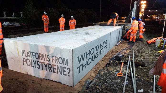
Platforms from polystyrene? Who’d have thought it?

MegaTech celebrates ten years of platforms with a difference

Next time you are standing on a station, waiting for a train, look down. Not at your feet – past those. What’s down there? On an older station it may be paving slabs, or tarmac. If it’s a newer platform, or a recent extension, it could be a fibreglass panel, or a concrete slab.

But what’s under that? Rubble fill retained by a brick wall under the platform coping stones? A complex arrangement of piled steel sections and cross braces with a glass-reinforced polymer (GRP) deck on top?

If it was built in the last ten years, it could even be a block of expanded polystyrene. You know, the stuff that TVs come packed in when they are delivered in a box.

It seems an unlikely material to use for station platforms, but, actually, it’s a good choice – easy to install and simple to modify.

An idea

It all started over ten years ago. A chartered surveyor named George Rowe saw expanded polystyrene being used to fill voids under platforms in the Netherlands, and thought it was a great idea.

Up to then, George had been leading a double life. He joined Tarmac Major Projects in 1986 as a trainee quantity surveyor. Working first at the Faslane naval submarine base on the Clyde, and then at the Royal Naval Armaments Depot at Coulport, he had been spending one month in three at college in Croydon, where Tarmac trainees from all over the country gathered centrally for the academic part of their training.

At the same time, George was a semi-professional footballer. He trained with local clubs wherever he was working around the country, but at weekends he was back in Scotland, playing for Clydebank, Queen of the South, Arbroath, Stirling Albion and finally Partick Thistle. While at Queen of the South, George also spent 18 months as the player/manager, being the youngest league manager in Britain at the age of 29.

By this time, George had left Tarmac and was working as commercial director with railway contractor QTS.

When he saw the Dutch platform, George thought that the simple idea could have applications in the UK, which was just embarking on a programme of renewing and extending station platforms as new, longer trains started to come into service.

He spoke with the Dutch supplier, intending to use that company as a source both of technology and of material. However, when he approached Network Rail, he had a setback as the material wasn’t acceptable in the UK, so he had to re-engineer the whole product.

Improved technology

Expanded polystyrene (EPS) is naturally flammable, self-igniting at a temperature of about 450°C. However, additives such as hexabromocyclododecane (HBCD) give the foam flame-retardant qualities such that the material shrinks away from a flame and self-extinguishes when the source of the fire is removed.

The large blocks of EPS used for building platforms need to be protected from the weather and accidental damage. The original Dutch system used sheets of polyurea, bonded to the outer surfaces of the blocks. That also has a flash point of around 450°C and is self-extinguishing.

However, at Network Rail’s request, George sought out another material, finally selecting sheets of a cementitious material that both met the technical specifications and gave the product the appearance of cement, so fitting in with existing and surrounding structures.

Tests were carried out by Exova Warringtonfire, demonstrating that the new product complied with Network Rail’s standards.

Once the tests were completed to the satisfaction of all Network Rail Departments, including James Holland, Network Rail’s principal fire safety specialist, George’s new company MegaTech Projects was ready to take on its first real-world challenge.

Three stations on the East Grinstead line were to have platform extensions. Geoffrey Osborne was the chosen contractor and three different solutions were chosen. Oxted itself was to be extended using traditional techniques – a brick retaining wall with a rubble infill behind.

Upper Warlingham was fitted with a GRP deck, supported by a steel framework that had been piled into the ground.

Sanderstead suffered from poor ground conditions, so it was the natural choice for MegaTech’s new lightweight system. A 50mm sand screed was laid and the EPS blocks placed on top. These were topped off with a polythene membrane and the concrete slab.

Network Rail’s lighting, CCTV and long-line public address requirements were all incorporated into the precast slabs. Coping stones and a tactile strip were fitted and the platform finished off and lined out.

And that, as they say, was how it all began.

The first installation – at Sanderstead.

Supply chain

The experience of successfully delivering Sanderstead enabled George and the MegaTech team to fine-tune the design and to establish their supply chain.

Adams Design Associates of Hastings became MegaTech’s sole designer, sorting out not only the design of the finished platform but how the various components fit together. The EPS blocks and the concrete slabs have to overlap so that no two joins coincide. Some blocks are channelled to accept cables, or drainage, in which case manholes need to be left in the concrete slabs.

Cambridge North.

The EPS blocks, cut to size and with channels, holes and recesses in them to the Adams design, are supplied by DS Smith of Livingston, West Lothian.

Peter Duffy, a civil engineering and construction company in Wakefield, takes those blocks and finishes them off. The cementitious board, delivered from Warrington, has to be fixed to exposed faces – normally three sides on end blocks and two sides (front and back) for those in the middle. In addition, recesses, such as chambers under manhole covers and cable/drainage channels, have to be clad as well.

Interestingly, about ten millimetres of EPS is left exposed, sticking up above the cladding. This is the compression allowance, to give room for the block to be slightly crushed as several tonnes of concrete slab is placed on top, without it damaging or cracking the cladding.

Those concrete slabs come from FP McCann. Originally, they were ‘just’ platform surface slabs – the copers and tactiles had to be added. Now those are all cast-in too, though tactile strips from Viztek are still used on occasion.

The slabs also have an anti-slip finish and are thicker at the front than the back – the slope of between 1:40 and 1:80 encourages drainage towards the rear of the platform and again complies with Network Rail’s standard requirements.

While the civils plant on site is usually supplied by the contractor, MegaTech likes to use road-rail (RRV) plant from Readypower, as its drivers know the system and how it fits together.

In addition to Duffy, GK Railways, CSM Projects and Rainton Construction (Scotland) build the platforms and extensions on site. Hayward Contracts manufactures, supplies and erects all of the fencing and Wrightseal seals all of the exposed edges and joints. Even the job of lining-out the completed platform is entrusted to only one supplier, Lincs Lining from Lincoln.

Widening the platform at Bath Spa.

Bath Spa

Ask George what his most memorable job is, and he has several definitions of the word ‘memorable’.

One of the largest was at Bath Spa station, in amongst the World Heritage Site that is the city of Bath. Electrification was coming through, and there is a minimum distance allowable between the overhead wires and the edge of the platform canopy. At Bath, this would have been below the minimum and, at any other stations, the canopies would have been modified and cut back.

But not at World Heritage Bath.

Fortunately, however, Isambard Kingdom Brunel originally built the line using his broad gauge of seven feet (2,134mm). When the route was converted to standard 4’ 8.1/2” gauge (1,435mm) in 1892, having been dual-gauge since 1874, this left the two tracks ten feet apart rather than the usual six.

So, the plan was to move both the tracks and the platform edges closer together, while leaving the canopies in their original location. This would give extra clearance between the canopies and the overhead wire, now above the moved tracks.

One platform was to be modified at a time, leaving the other platform open so that a revised train service could operate, with trains between Bristol Temple Meads and London Paddington via Bath and Chippenham operating every hour.

The speed with which the MegaTech platforms could be erected was key to it all working.

Main contractor Hochtief asked MegaTech to handle all of the platform work, including lifting the original surface. This was a mix of Victorian paving slabs and tarmac. The plan was to lift and reuse as many of the Victorian slabs as possible, so that, when the new, wider platform surface went back down, it would be similar in appearance to the original.

On the weekend of 8-9 April 2017, Babcock removed the track adjacent to Platform 1. MegaTech moved in on Monday morning, stripped the platform surface, broke up the old platform underpinnings, laid the sand bed, positioned the EPS blocks, replaced the retaining wall so it would closely resemble the original and relayed the surface using as many old slabs as possible.

That was all finished on Friday night. That Saturday, Babcock replaced the track, then removed the railway next to Platform 2 on Sunday, which was Easter Day.

Bath Spa – one patfiorm completed, the other is work in progress.

Monday to Friday was a repeat of the first week. Babcock replaced the track on Saturday, Sunday was spent tidying up and commissioning, and the whole station reopened with new, wider platforms, which were now at the standardised height of 905mm above the track and 740mm from it, on Monday morning. What’s more, the new OLE wires, when they were installed, would be the regulation distance from the untouched canopies.

Uckfield

One property of EPS that is not normally needed when building a station platform is that it floats. However, at a station such as Uckfield in East Sussex, which regularly floods above the platform height, that could be a problem. What would happen if the natural buoyancy of the EPS was more than the weight of the concrete platform slabs? Would the whole thing just float away?

Uckfield – gaps were left between each block so that floodwater could flow more easily.

MegaTech’s designers and installers had an answer to that. For a change, they didn’t butt the EPS blocks up against one another – they left a gap, facing all four sides of each one. This allowed the floodwaters to pass through the platform and reduced the total amount of (buoyant) EPS. The concrete slab was also thickened into ribs that fitted down into the gaps, both locking the blocks in place and adding weight.

Finally, Platipus ground anchors were driven through the platform surface slab, passing down through the gaps and three metres into the ground, locking the assembly in place. It wasn’t going to go anywhere!

Uckfield – installing a Platipus anchor.

Short access times

One of the two platforms at South Hampstead station, between London Euston and Watford, had suffered from retaining wall heave in 2013. This pushed the footings out and forced Network Rail to close half of the platform, only using the other half.

With the added complication of a high-voltage cable running through the platform, and work access limited to only two hours each night, with no time available at weekends, that half of the platform stood unused for two years.

Half of the platform at South Hampstead had been unused for two years.

Finally, J Murphy & Sons was brought in to rebuild it, and MegaTech was asked to undertake the platform work using its EPS system.

The first task was to demolish the damaged platform and survey the footings. These contained cast-in concrete ribs that, although they could be cut back by hand, couldn’t easily be removed entirely. The solution was to cut the EPS blocks to fit, and cast the concrete slabs to fit them. This resulted in 26 slabs – every one of which was different.

The blocks and slabs were prepared in a Murphy compound nearby, then brought to site in the correct order. The platform was rebuilt between late-January and April 2015, a three-month period that only allowed a total of 45 hours of access – on one night it was just 50 minutes.

Access was also a problem at Newark Northgate, this time it was just six hours a week, all on a Saturday night. A timber 28-metre platform was to be extended by 38 metres. As the existing timber trestle was in poor condition, MegaTech and principal contractor Carillion were asked to replace the whole thing. However, the train operator required at least 28 metres of platform, an equivalent length to the original structure, to be available at all times.

To achieve this, work was planned in three six-hour possessions over three weekends. Every section had to be complete at the end of the shift so as to comply with the train operator’s requirements.

Watford Junction was another station with an old wooden platform – Platform 11. It was replaced over Christmas, with the last train calling late on Christmas Eve and the first train using the new platform on the morning of 27 December, just 54 hours later.

All of this is a far cry from building a new station, as MegaTech did for VolkerFitzpatrick at Cambridge North. 1,000 metres of new platform on virgin ground – a doddle!

Success breeds success

One of the more successful results of a MegaTech platform extension came at Slough. Working to an overall design by Amey Consulting, MegaTech was asked to  extend two platforms, one by 100 metres and one by 70 metres, which it did in 36 hours.

The visible speed and success at Slough meant Network Rail’s response was to cancel the partially completed, traditional design at Maidenhead station (in March) and have it reissued, specifying the MegaTech EPS. Amey Consulting worked with Adams Design Associates to rework the design. Installation commenced in August and was complete by September, more or less when it was originally required. Network Rail had clawed the overrun back.

It’s a cracker

But ask George Rowe what the best project that MegaTech has completed is, and his answer is surprising – Ulceby station rework, Saturday 7 September 2019, for a fee of just £10,000.

Ulceby – using an excavator to push the slab forward into position.

Really?

MegaTech had extended Ulceby, which lies on the Barton line in Lincolnshire and is served by trains between Cleethorpes to Barton-on-Humber via Grimsby and Immingham, in 2015 as part of Siemens Mobility’s North Lincolnshire resignalling and control project.

The platform extension was completed as planned. However, the railway line through Ulceby was undulating, and the extension followed that line (905mm high and 740mm from the track).

A couple of years later, Network Rail upgraded the track, smoothing out the undulations and slewing it over, which now made the EPS platform too low (by up to 60mm) and too far from the track by 30mm. To conform to standards, it had to be moved outwards and raised up.

Using any other system, the whole platform surface would have to come off, the underpinnings modified, and then the surface reinstated, a major job.

Ulceby – lifting the patform surface using bottle jacks.

Instead, MegaTech did it in one evening with an excavator and four bottle jacks.

First, the excavator got behind each concrete platform slab and gave it a shove, moving it out 30mm.

Then, using the bottle jacks, each slab was raised up by about 70mm. A spacer of the correct thickness, already faced by the cementitious material, was then slid into the gap and the slab lowered. Job done.

It was quick, easy, cheap, and really demonstrated the versatility of the MegaTech EPS system.

It was also almost exactly ten years since MegaTech installed that first platform extension at Sanderstead.

Happy Birthday, MegaTech!

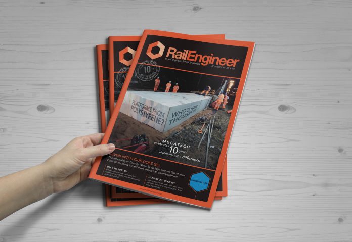
Rail Engineer October 2019: Megatech polystyrene platforms, Thickley Wood footbridge, Headspans to Portals, HS2 high-speed tunnel portal design

Learning from others

It is always good to learn about new techniques and innovative rail technology. This month’s magazine has many such examples, as well as international insights from Edinburgh and Moscow.

Around 120 papers were presented at the recent engineering conference in Edinburgh, at which over half the participants were from outside the UK. Examples of the in-depth international technical papers included on asphalt track beds (USA), pre-packed concrete slab track renewal (Japan) and the longevity of masonry bridges (Australia). Many delegates felt it was worthwhile to fly half-way around the world to present their papers and learn from others present. This raises the question of what Britain’s railways can learn from such events.

Russian Railway’s biennial Expo 1520 provided another international learning opportunity. The conference programme included much about the fourth industrial revolution and plans to take advantage of it. Indeed, the event started with a demonstration of artificial intelligence in the form a self-driving train.

Presentations from Alstom included hydrogen trains whilst Siemens highlighted its Thameslink ATO overlay on ETCS level 2. Both companies have done much to modernise Russia’s trains. However, their contracts for the provision of new trains stipulate developing the Russian supply chain to produce high-value train components.

Clearly Russia’s rail industry has learnt much from Europe, yet what can be learnt from them? One answer may be track recording systems, which include ultrasonic inspections at 140km/h while Network Rail’s ultrasonic rail inspection challenge statement aspires to increase its current 50km/h inspection runs to 100km/h.

Another area is train control systems. Russian Railways has about 30,000 GPS-linked KLUB-U cab signalling systems in use and plans to introduce moving-block signalling by 2027. From a UK perspective, this large-scale deployment of the Russian ETCS equivalent is impressive. No doubt, this is supported by a strong guiding mind, which ensures that there is an effective systems approach across the wheel/rail interface.

Whilst the UK’s ETCS deployment is relatively modest, as Clive Kessell explains this month, Network Rail’s Signalling Innovations Group has progressed various worthwhile initiatives, many involving analytics and big data. In another feature, we describe how data management is fundamental to the success of Building Information Modelling (BIM) on London Underground’s Northern line extension. 

Advanced analytics is also being used in a new water events prediction application. As Paul Darlington describes, this should reduce the number of earthworks failures. An innovation that does not involve data analytics is the use of expanded polystyrene to build station platforms. Nigel Wordsworth describes the benefits of this technique and explains how it was developed.

Innovations for rail decarbonisation, and in particular hydrogen power, are a topical subject. Simon Meades reports how this is now being used to power, not trains, but on-site generators to reduce both CO2 emissions and noise levels. Another decarbonisation innovation is, we think, the world’s first use of solar power to directly supply a rail traction system. Stuart Marsh explains how this Riding Sunbeams initiative is powering the DC third rail around Aldershot.

Although electrification is the best way to decarbonise the railway, on today’s busy railway it must not fail. Peter Stanton has been considering the reliability issues associated with OLE headspans and reports on an initiative to convert them to portals.

Thickley Wood footbridge spans what was the historic Stockton and Darlington Railway at Shildon. As Bob Wright states in his report, the footbridge reflects the growth and decline of the coalfields around the area. As there was no longer a railway below much of the old seven-span bridge, its recent repair involved three spans being replaced by an embankment.

From the world’s first steam-hauled public railway to Europe’s newest high-speed railway, Keith Fender describes the 60-kilometre Danish high-speed line which opened earlier this year at a cost of €1.6 billion and will eventually operate at 250km/h. Whilst this might seem cheap for a high-speed line, it has only one station, few major structures and just one tunnel. Nevertheless, tunnels on high-speed railways can be problematic – as Grahame Taylor describes, they may require hoods and trains with long noses.

Graham Neil clearly thinks that it is important to learn as much as possible about the industry. As the new chairman of the IMechE Railway Division, he recently gave his address ‘All change and mind the gaps’, an unsurprising title as he is also TfL’s professional head for vehicles. In his report, Malcolm Dobell explains Graham’s concerns about the skills, Brexit, economics, technology and IMechE/railway gaps that need to be minded. 

Bridges for these gaps include the requirement for all in the industry to do their bit by encouraging young people to consider a railway career. Meanwhile, the Railway Division must work with industry to provide more relevant events to encourage learning and development.

One Railway Division event at which young engineers learn much is its annual Railway Challenge, on which we report this month. As it was won by a German team, while the Polish team’s locomotive won an award for engineering elegance, this event also proved to be another opportunity for international learning.

Making user-worked crossings safer

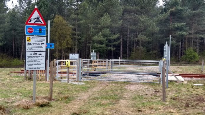
User-worked crossings (UWC) are intersections where a railway crosses a right of way such as a road on private land, a footpath or a bridleway. Any gates or barriers provided often need to be operated manually, with some crossings requiring users to telephone a signaller to check that it is safe to cross.

The rate of collisions and fatalities at these types of level crossings is higher when compared to other level crossings when the usage rate is taken into account. Often, the only technology to assist the user is a sign informing them how to operate the crossing. However, work is now underway to improve the signs and reduce the risk of such crossings.

When the railway was first built, the former railway companies were required to provide access across the railway for those affected. Where this resulted in the construction of a level crossing, it was operated by the user, and unless the landowner has agreed to give up their rights to use it, it is still the responsibility of Network Rail to maintain the crossing for the safe benefit of all users. The owners of the land and those who also have a legitimate right to use the affected road also have a legal right to use the crossing.

User-worked crossings were also required to maintain access between lands severed by the railway where a roadway or track did not previously exist. The most common being the field-to-field crossing. Along with footpath and bridleway crossings, these types of crossing present one of the greatest safety risks to today’s railway, with the user responsible for making sure it is safe to use the crossing and for opening or shutting any barrier or gates provided.

An existing crossing – Kings Mill Lane level crossing, Ashfield, Nottinghamshire, in August 2018

Diverse users

For many years, users of UWCs were generally local and familiar with the operation of the crossing. Trains were also slower and noisier than they are today.

In recent times, the profile of users has diversified significantly. They are no longer just the local landowner, farmer, postman or shopkeeper. Users now include a wide range of couriers, delivery drivers and members of the public, many of whom are unfamiliar with how to use these types of level crossing safely and who may not have English as their first language.

Users are also likely to be ‘connected’, using headphones or texting on their phones. They may have mobility issues or be riders on horses or bikes. Tractors are faster and drivers are likely to be in noise-reducing cabs, with the heating or air-conditioning fan running, and be incentivised to move quickly to increase productivity.

On top of all this, trains are now often more frequent and are considerably quieter.

There are around 2,500 such private crossings in Great Britain, representing more than a third of all level crossings on the network. The Rail Accident Investigation Branch (RAIB) published a report on its investigation into a fatal collision in October 2017 involving a high-speed train and a delivery van at a private crossing at a farm in Teynham, Kent. This recommended that the government, in conjunction with the Office of Rail and Road and Network Rail, should review and revise signs at private crossings so that they clearly and unambiguously convey information and instructions on how to use the crossings correctly.

The technology available to the rail industry to manage level crossings and enhance protection has also developed in recent years, such as through technical advances in miniature stop lights (MSLs). However, the signage at crossings has not developed at the same rate, and this presents a potential safety risk to members of the public. To improve safety at these crossings, Network Rail is now working closely with the Department for Transport (DfT) and the Office of Rail and Road (ORR) to revise and make improvements to the signage provided at UWCs.

RSSB report T983

The work started with the production of T983 – Research into signs at private level crossings – by RSSB. This considered, from first principles, the types of signs that should be presented to users at UWCs, including those at field-to-field farm crossings. The project explored which signs and signals best convey the particular points of information that users need when approaching these crossings.

New high-level instruction sign.

It made use of the methods and findings of a recently completed project examining signs and signals at public road crossings, and drew on good practice in signage in general and in the railway environment in particular. Existing signs at level crossings were compared with good practice and, where it was judged that they were not the best solutions, other signs were considered.

The project focused on proposed improvements to signs and markings, and carried out an initial evaluation of the proposed improvements and identified barriers to implementation. It was identified that users did not always associate the existing user-worked crossing sign with the crossing being approached. The sign was too ‘wordy’ and did not use a pictorial representation of a crossing.

As a result of the research three types of draft signage were proposed with simple, clear and unambiguous instructions, and making good use of pictorial icons:

  1. Universal user-worked crossing ‘triangle’ sign. The proposed sign, unlike the existing signs, shows the three separate crossing elements as icons: a train, a gate and a railway track.
  2. High level instruction ‘blue’ signs to inform users to ‘Stop look and listen’ or to ‘Stop and telephone’.
  3. Detailed instruction signs. These would have a mixture of illustrations and text to clearly instruct users.

T983 identified that it was important that the proposed signs were legible and well understood, or it could make matters worse instead of better. It recognised that, while the proposals may be clear when viewed on the desk or on a computer screen, trials were recommended to compare the legibility of the designs with the current instruction signs.

The trial site at Cannock Chase, Staffordshire.

Trial evaluation

Network Rail is now involved with all stakeholders to take forward the benefits of the T983 report and to implement a ‘root and branch’ review of the UWC signs proposals in a systematic way, to establish where and how the improvements can be made. The three proposed signs produced by RSSB were reviewed in workshops at which specialists, including route level crossing managers, representatives from DfT and ORR and with signage experts, discussed everything from level crossing risk to ergonomics.

The proposed signs were produced by Royal British Legion Industries (RBLI), then installed and trialled at a user-worked level crossing ‘mock up’ site which had already been established by the ORR and Network Rail at Cannock Chase, Staffordshire. This is a facility used as a training resource for those organisations who regularly come into contact with user-worked level crossings.

Five different crossing types were evaluated, including common and complex types of UWC. These were non-telephone UWC, telephone UWC, power operated gate opener (POGO), MSL and a POGO MSL crossing.

The site consists of approximately 12 metres of track that leads nowhere and with no trains involved, but it is so realistic many visitors believe it is a real railway. Most of the required infrastructure was already in place, although a POGO had to be installed. The Transport Research Laboratory (TRL) had assisted RSSB in the T983 report with virtual reality modelling, so TRL was also employed by Network Rail to facilitate the trials and to provide continuity with the process.

Initially, 15 different users per day for three days of all ages, gender and abilities were involved with the trials in April, with another similar trial a few weeks later. The users were people who were all unfamiliar with any type of UWC. Some people went over each crossing type as pedestrians and others as car drivers.

One initial finding was that people used the crossings in various ways, even if all of them were safe. Users were fitted with head cameras and asked to complete a questionnaire – all the captured data will be subject to qualitative and quantitative analysis before the recommendations are finalised. This will include the format, the size of the signs, font and icons, together with a Welsh version. One change to the T983 report proposals already identified is that the icons on the signs will be at the top and read left to right, rather than vertically on the left.

Further trials are planned with users who are familiar with the operations of UWCs.

Implementation

The first operational installation trial is planned for Jacky Duffin Wood crossing, a UWC POGO MSL on a freight line on the London North East route.

Once all the captured data is analysed and evaluated, the plan is to republish the Network Rail standard for level crossing signage, and any other standards affected, with the new signs available from early 2020. They will be then deployed on the various Network Rail routes, using their local knowledge and crossing risk profiles and liaising with project teams which may be doing work in a particular area.

New legislation will also be required to amend the Private Crossings (Signs and Barriers) Regulations 1996, however Network Rail is working closely with the DfT so that there should be nothing to prevent the new designs being brought onto the network in 2020 via a nationwide trial authorisation process.

The new signs will be enforceable during the nationwide trial period.


This article first appeared in Issue 177 of Rail Engineer, Aug/Sep 2019.

Safer, quicker and sustainable cable protection

As the world, and the railway, goes more and more digital, the big growth industry seems to have been in the production of cable. Offices are festooned with cables linking computers, servers, storage devices, alarms, CCTV cameras, printers, scanners and a host of other devices. Every desk has the potential to have a ‘rat’s nest’ of cables lurking underneath it.

Homes are no different. To the cables linking computers, routers, printers and scanners can be added the ones to TV sets, control boxes, recorders, speakers, CD players and satellite dishes.

One solution to this is, of course, to make as much as possible wireless. Many devices now use Wi-Fi, Bluetooth or infra-red technology to get rid of those annoying cables.

Cable protection

The railway has the same problem. Some wireless technology is creeping in, but there is no solution to the need for power cables – both traction and signalling power – as they cannot be replaced. Communications cables, for signalling control and other functions, are often also needed for security and reliability reasons.

Braintree, Essex.

So, the side of the railway starts to look like the side of an office desk – cables, cables and yet more cables.

These cables need protecting. Traditional methods see ground-based cable troughing used. However, where there isn’t a clear walkway alongside, the trough lids are often walked upon. If the route is not of designated walkway width, this practice can be rather unsafe and, with slips, trips and falls maintaining their number-one spot in workplace incidents, it’s a risk that needs to be reduced.

And, of course, the manual handling of cable troughing has to be carried out safely and within prescribed weight limits. Solutions to improve this element of the project are very welcome.

There are two solutions to these problems. The first is to make the troughs from lightweight polymer materials – several different solutions now available.

The second is to elevate the trough above the ground on posts. Then, no matter the angle of the side of the embankment or cutting, the trough is safely above it all. It also can’t be walked on – another plus – and presents cables for maintenance at waist height, making things simpler for the maintainer.

Network Rail prohibited the manual handling of metre-length C/1/43 ground-based concrete troughing units in 2014. Since then, the industry has kept a very strict eye on the installation of cable troughing and any methods introduced to reduce the risk to workforces were, and still are, very welcome. With this in mind, Scott Parnell worked in partnership with Complete Composite Solutions to introduce the UK to a revolutionary product which was already leading the way across Europe with full approval by Deutsche Bahn.

Innovative system

ArcoSystem is the only elevated troughing system in the UK which can span six metres between post centres. Already fully approved by Network Rail, the product offers a reduction in hole centres (versus traditional elevated systems) of up to 75 per cent. This saves workforces from the process of digging out foundations, mixing postmix and water, and installing the posts every 1.5 to 2 metres, as is the case with traditional systems. With this reduction in post centres, there is also a decrease in the risk of cable strike, which can occur during any ground penetrating installation.

The ArcoSystem troughs are made from a lightweight, pultruded, twin wall fibre-reinforced polymer (FRP), which provides the strength to support each length over six metres. In addition to this, it means the overall weight of each six-metre length is under 36kg, making them safe for two people to lift easily.

The reduction in post centres not only protects workforces, but also decreases installation time by up to 60 per cent. As possession times get more and more congested, with more contractors having to share track time, this saving is invaluable.

ArcoSystem not only works well as a foundation-installed elevated route, it also interfaces seamlessly with the complicated rail infrastructure. Transitioning from ground-based troughing up to an elevated route then back to a wall mounted system is easy. Alternatively, it also works perfectly for a suspended route by utilising handrails on one of the many walkway systems. The system should be hung on the outer edge of the handrail to prevent the safe walking area being reduced in size.

Should the standard range of ArcoSystem not be suitable for certain areas, Scott Parnell will work closely with project designers, engineers and construction teams to develop bespoke units to fit, no matter what the infrastructure is that’s presented to them – versatility at its best!

ArcoSystem has now been present in the UK’s rail sector for three and a half years and has been used on some major schemes, from Crossrail Anglia and Weaver Wavertree resignalling to, more recently, HS2 enabling works at Euston. In such a short space of time, it has become a popular choice amongst contractors with over 125km of route now installed on the UK’s railway network.

Safer installation

Although Scott Parnell has seen ArcoSystem go from strength to strength, the company has certainly not just sat back and rested on its laurels. It has also worked on creating an installation technique which was even safer for workforces to implement. Following an overview of the entire installation process, Scott Parnell identified areas for improvement and enhanced these accordingly.

ArcoSystem offers a vast reduction in manual handling by reducing the number of holes installers need to dig into the ground for post foundations. As the six-metre distance between post centres cannot be expanded, the maximum saving in manual handling is achieved. Furthermore, it is not possible to reduce the weight in the system components without affecting the integrity of the product. Scott Parnell will never compromise on quality, and therefore it was realised that improvements were possible and would be made. Stand by for the innovation of the year…

For each post foundation which is embedded into the ground, approximately 60kg of postmix is used, along with around 20 litres of water to mix it. This process, which has not changed since elevated troughing was first introduced into the rail sector, is one which is almost always done manually, without the aid of machinery. It therefore has a considerable musculoskeletal impact on the installation teams, especially those gangs installing troughing systems shift after shift, project after project.

Introducing Techno-Crete

To combat this problem, Scott Parnell has introduced Techno-Crete, a new product that provides an innovative solution by replacing the need for both postmix and the associated water, around 80kg of product, with just 1.6kg!

To put this into perspective:

  • 1km of traditional two-metre span troughing requires 30 tonnes of postmix;
  • 1km of ArcoSystem six-metre span troughing, with only one third the number of posts, takes 10 tonnes of postmix;
  • 1km of ArcoSystem six-metre span troughing, installed with Techno-Crete, needs just 267kg of Techno-Crete.

Techno-Crete is revolutionary in the reduction of manual handling, but the benefits of this innovative product do not end there. With a curing time of just 20 minutes, Techno-Crete can decrease the installation time of ArcoSystem even further.

Where postmix has traditionally had a curing time of 24 hours, this has meant installation teams have had to plan work carefully and revisit site again to install the trough route onto the posts once the postmix has set. However, one recent installation using ArcoSystem with Techno-Crete resulted in 22 metres of route being installed within just four hours – all while workers were being suspended from ropes down a steep embankment!

Techno-Crete also has sustainable benefits. It is manufactured using 85 per cent recycled and sustainably sourced vegetable and rapeseed oils. This is a key advantage as CP6 begins, which has the toughest sustainability targets the sector has ever seen.

The CO2 saving compared to postmix is over 70 per cent – approximately 10kg of CO2 per post foundation. Just 100 foundations using traditional postmix would require six tonnes of concrete to be used. Also, at the end of its life, Techno-Crete can be crushed and fully recycled into products such as precast concrete.

Techno-Crete is delivered to site in a two-part set – ‘Bag A’ and ‘Bag B’. When the foundation is ready, the two bags are opened and one poured into the other. A vigorous shake will mix the two components together and then the mixture is poured into the ground. Within 10 minutes, the product will expand to twenty times its original size and within twenty minutes the mix will have set. Health and Safety protocols are no different to that for the application of postmix, and transportation and storage costs are both dramatically reduced.

Scott Parnell’s new Techno-Crete is also ideal when used as a foundation for a variety of railway systems, from handrails to fencing and DIS boxes. Anywhere postmix can be applied, Techno-Crete can be used as an alternative.

Using TechnoCrete.

Innovative supply

Sharon Rice, national rail manager at Scott Parnell, said: “The UK’s rail industry has been aware of the implications that manual handling has on its troughing installation teams for some time and huge progress has been made to improve this. At Scott Parnell, we have worked tirelessly to make sure we do our best to support this movement. For example, we were one of the first to provide six-metre length GRP troughs which sit comfortably within safe weight limits for two people, reducing not only the weight, but number of lifts required during installation.

“With the introduction of Techno-Crete, we are taking things one step further by eliminating the need for three 20kg bags of postmix, which are currently required to install each individual post. Posts are often positioned in difficult to reach locations meaning that postmix, and the large water quantities needed to mix it, causes a huge manual strain on workforces and often requires a costly RRV to get it to the installation point. One box of Techno-Crete weighs far less than a single bag of postmix, meaning that one person can easily carry the material for up to 12 foundations in a single lift.

“With all this in mind, Techno-Crete has the potential to make a real difference to the rail sector and the way construction and improvements are carried out. In particular, the reduction in time to complete projects and the resulting safety benefits of quicker installation and manual handling makes it ideal for possessions”.

With innovations such as this, it is clear to see why Scott Parnell is the supplier of choice for the rail industry.

Transformers Aluminium or Copper?

Guest writer: Paul Walker

There is a drive on the rail infrastructure to reduce the overall cost of signalling power and other installations and increase electrical efficiency. One of the main tenants of this philosophy is the use of aluminium due to its low cost. As such there is also a drive to use transformers with aluminium windings to reduce costs further.

FT Power Transformers have taken on the challenge of producing aluminium transformers for trackside infrastructure in the 500VA to 100kVA range.

But is aluminium (Al) really so much better than the traditional copper (Cu)? Below is a base table of the pro and cons of both aluminium and copper transformers, based on both experience and research.

Conclusions

These studies have led FT Transformers to believe that large aluminium power transformers have advantages over similarly sized copper units when it comes to cost and weight. The efficiency of the units is about the same.

However, small trackside units that are rarely maintained will, over the life of the installation, suffer from increasing levels of resistance due to aluminium oxide. This will be a future issue for current trackside transformers, particularly for signalling power units, and will show up as an insulation fault at the permanent insulation monitors (Bender units located with the Principle Power Supply buildings) for the signalling power class II IT feeders.

Regular inspection and maintenance will be required. However, once a signalling power feeder is commissioned, it is often not maintained until there is an issue.

Therefore, it is FT Transformers’ opinion that the life of signalling power feeders will be greatly reduced using aluminium, increasing the whole life cost.


Paul Walker is a mechanical design engineer with FT Power Transformers.

Further Reading:

Edvard Csanyi – Aluminium vs. Copper: Conductors in Low Voltage Dry Type Transformers (Electrical Engineering Portal, October 2010)

Hans De Keulenaer – Reliability of Terminations: Copper vs Aluminium (Leonardo Energy, August 2018)

Ronaldo Bertoldi – Aluminium vs. copper conductors in transformer manufacture (EE Publishers, March 2017)

Tahir Ayub – Eliminating Copper, the next step (Rail Engineer, July 2017)

Powersmiths International Corp – Transformer Inrush Currents and Protection (Critical Power Group, June 2013)


This article first appeared in Issue 177 of Rail Engineer, Aug/Sep 2019.

Sustainability and Decarbonisation: What are transformer losses?

Guest writer: Neville Haide

It is a good question, and one that needs to be answered and better understood by a wider audience within the rail industry. The perpetual transformation of electrical energy into thermal energy is seen within a transformer’s two main loss components. The off-load standby losses derive from reversing magnetisation and eddy-currents within the core. These losses can be reduced heavily with the quality of core material and designed levels of flux density.

The on-load losses are, in the main, generated from the ohmic resistance of the transformer’s nonferrous windings under load and can similarly be reduced with good design practices. A transformer’s core loss can be compared to an electric heater, guzzling electrical power continuously and so transforming electrical energy into wasted thermal energy. With a transformer, this also happens in a standby state, with no inductive or resistive loading present. A 60 per cent reduction in standby power losses is easily achievable and has been demonstrated as being commercially viable.

London Bridge REB.

It should be noted this is not a great discovery, nor some revolutionary new technology. Rather, it is the adoption of efficiency-conscious design methodology. In the case of a points drive transformer rectifier, energy is being thrown to the wind even when the points are not moving, so why are we still deploying low-efficiency magnetics into these systems and other power distribution networks?

The UK must hit a CO2e (carbon dioxide equivalent) reduction target of 38 per cent by 2030. This, in part, can be achieved with the enhancement of standards and legislative requirements to the supply chain and system designers.

Traction power demand annually is around 3,400GWh alone, taking into consideration a highly saturated legacy network of mainly low-efficiency magnetics.

Studies show that at least three per cent of the power generated in the UK is wasted energy from the losses in transformers.

To put this into context, around 102GW of traction power could be attributed to the wasted energy of its associated magnetics. This is the equivalent of unplugging the domestic supply to around 30,000 homes in the UK for a whole year.

Decarbonisation schemes focus heavily on the development of new technology to support a reduction in future carbon emissions. High-efficiency solutions already exist, but they are not being considered by a large majority of regional projects. Why is this? Is there a lack of understanding of the technology, a culture of ‘copy and paste’ engineering or the age-old commercial driver to satisfy a project at the lowest possible cost?

Either way, selection of the cheapest or oldest products available for an electrical system do so to the detriment of that system’s whole life efficiency. Whole life cost assessments favouring high-efficiency equipment demonstrate unarguable carbon reduction and energy savings.

Despite this data, competitive tendering governed by awarding bodies and the flexibility of standards continue to drive the use of high carbon output solutions. Industry leaders who rethink the selection of products for the power networks with an Archimedean point view of a systems efficiency, environmental impact, and whole life cost can make significant changes for the future.

Top-level commitment in CP6 by route asset managers, principal designers and those organisations that demonstrate best practice in the development and/or deployment of low-carbon solutions can align together to deliver a strong, traction-carbon reduction framework for CP6 and beyond. Significant carbon reduction and energy savings over the life of a power distribution system, while safeguarding the environment for future generations, are attainable if we consider the ‘low hanging fruit’ solutions and technology already available to us.

The world we leave for our future generations must not be one heavily harvested of its depleting earth reserves when widely available alternatives exist. Alternative sustainable solutions for electrical conductors need also be deployed and not just seen to be discussed.

Bauxite, the ore used to produce aluminium, is the most abundant ore on our planet, yet we continue to harvest depleting copper reserves that some environmental analysts predict, with a growth in demand of just two per cent, will be commercially exhausted within the next 25 years.

A coherent policy is needed that considers, where practical, high-efficiency products, and those with advancements in the application of alternative sustainable materials. These should be adopted by all responsible manufacturers, system designers, and project delivery institutions if we collectively are to meet our environmental obligations and targets.

Neville D Haide is managing director of ATL Transformers.


Advanced magnetics supporting industry

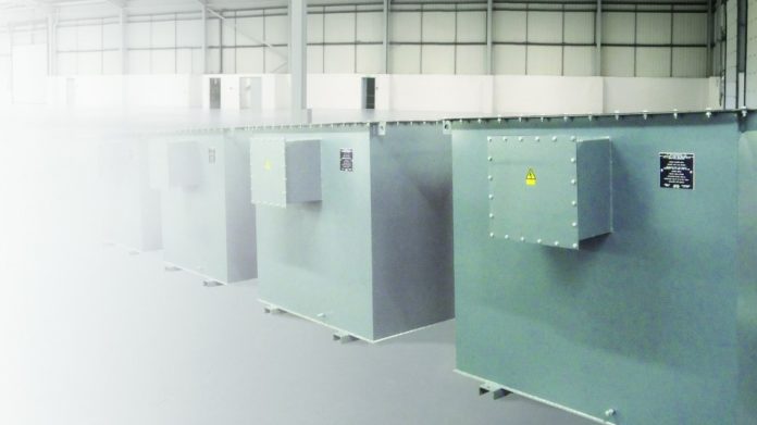
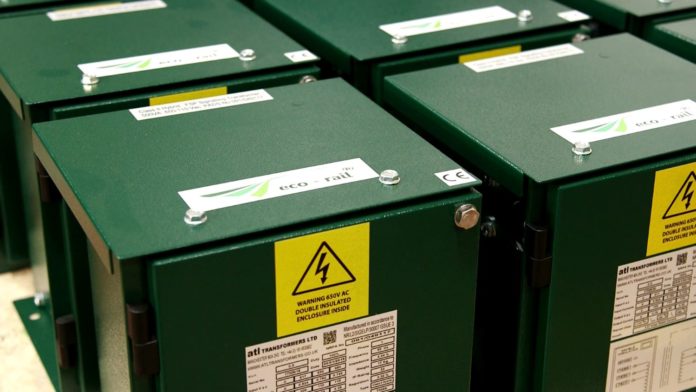
Siemens adopted the ATL Transformer ‘aluminium’ range for its new Westlock WESTRACE Trackside System (WTS) as that move aligned with the copper-reduction strategy championed by Network Rail. The aluminium range also provided CDM benefits with significant weight savings and an increase in reliability.

The team at ATL Transformers worked closely with the Siemens WTS team in developing the new range of products, which was first adopted as part of the Thameslink London Bridge Area Partnership Scheme, completed in 2018.

Following the Thameslink scheme, ATL transformers and transformer rectifiers have been adopted on all WTS schemes that Siemens have commissioned, including on Weaver to Wavertree, Liverpool Lime Street, Derby remodelling, Victoria 2B and Huddersfield to Bradford Resignalling.

Following these numerous commissionings, there have been no in-service failures of the ATL transformers, demonstrating how reliable this new product has been.

 Gary Taylor CEng MIET, engineering manager – power engineering, Siemens Mobility.


Unique transformers support leaner design

ATL Transformers, as a product and as a company is indeed fantastic. I first came across their low-inrush transformer range during the development phase of 4LM (4 Lines Modernisation – the resignalling of London Underground’s sub-surface lines) Wayside LVAC power supply design.

We were in need of finding a working solution to our individual radio power supply inrush-current problem and the inrush limiters on the market just did not do the job – either they were not in range or their RAMS (reliability, availability, maintainability and safety) figures were too low. As hundreds of these are powered from the same network, their x16 inrush has created a rather big problem for protection settings and discrimination.

ATL proposed its unique range of transformers which have helped to eliminate the problem with the excellent 1.96x FLC figure. The company’s knowledge and support throughout the project were spot on, its factory testing facility and scheduling flexibility helped save the day and, with our combined effort, we were able to provide a leaner design without the need of any individual inrush limiters.

If a similar situation would occur on any other projects of mine, I would not hesitate to contact them immediately as the very first company in mind.

Istvan Bazsinka CEng MIET, project design authority, Thales.


A knowledgeable and supportive supplier

Throughout the large portfolio of rail engineering projects that we have worked on or are presently working on at Amey Consulting, we have built very good relationships with suppliers and manufacturers that support us in the specification and selection of innovative products and technology.

In the world of electrical power on the UK railway, Amey Consulting has successfully designed and commissioned several signalling power upgrades for reliability, resilience and enhancements. As part of this success, and the present work bank we have, we work very closely with ATL Transformer’s rail segment.

ATL has been very supportive in providing Amey Consulting with product solutions to support its energy management targets and global sustainability goals, in particular ‘Goal 9’ and ‘Goal 13’, which are ‘Industry, Innovation and Infrastructure’ and ‘Climate Action’ respectively. The design work Amey Consulting E&P has produced for signalling power projects include the use of ATL’s Rail Signal Transformers and PSP/ASP Transformers.

The new generation of eco-rail® transformers, that have been made available to us from ATL, have characteristics that contribute to the safeguarding of the environment as they are ultra-high efficiency, reducing the carbon emissions and environmental impact. These transformers also present low standby losses which support the reduction in wasted energy.

The latest aluminium range not only supports copper elimination, a major sustainability target, but it also offers a 30 per cent reduction in cost and weight, making the transformers easier to transport and install on projects being designed by Amey Consulting.

As part of our product research and specification of electrical power products, Amey Consulting has attended several CPD (Continuous Professional Development) sessions and exhibitions to support the personal development of staff and the business. ATL’s Neville Haide has been a great supporter of this, delivering sessions at our offices and practical sessions on hassle-free installation solutions at exhibitions.

Amey Consulting has been one of the first E&P design consultants in the UK to design and implement a signalling power distribution system using the new ATL slim, aluminium, lightweight supply transformers located inside principal supply points, resulting in a reduced footprint.

ATL has worked with Amey Consulting, manufacturing bespoke solutions to provide a ‘plug and play’ system, as required by the client. It has been a pleasure to work with such a knowledgeable supplier that gives the time and effort to ensure they meet their customer’s requirements.

As the rail industry has a history of lengthy processes when seeking product approvals for newly innovated solutions, this did not deter the collaboration between Amey Consulting and ATL as both organisations have built a reputation and trust within the industry and approvals was the least of our concerns.

Amey Consulting has several objectives, one of which is a sustainable growth of the business. This objective is related to employee development. In addition to all of the CPD and technical support we have had from ATL, we are also looking at the ATL Training Academy for our apprentices, trainees, graduates and experienced engineers.

Abdul Rehman Savant CEng MIET, senior electrical engineer (E&P Design CRE), Amey Consulting.


This article first appeared in Issue 177 of Rail Engineer, Aug/Sep 2019.

Anglia OLE renewals: success through collaboration

Guest writer: Caroline Bacher

Since 2007, Network Rail has steadily been replacing the overhead line equipment (OLE) on the Great Eastern line from London Liverpool Street, first to Chelmsford and then on to Southend Victoria. The old system had reached the end of its lifespan was increasingly becoming a reliability issue.

A key goal for the project team was to reuse as much of the existing infrastructure as possible.

Working with OLE specialist Furrer+Frey, Network Rail developed a new, auto-tensioned, modern 25kV AC system that retained a vast number of existing steelwork structures in order to save costs, reduce risks and minimise disruption and impact on service. It also aimed to address known reliability and performance issues, and in such was tailored to the region and its specific challenges.

Upon completion of the new system’s development, a rolling programme of electrification renewal was undertaken on this route and, after 10 years, is due to finish. Once some initial teething issues were ironed out on the first few sections, both design and installation went smoothly and without major drawbacks as the teams grew closer together and the supply chain worked well on all levels. Furrer+Frey and the Network Rail in-house installation team OCR were working hand-in-hand to deliver the renewals without major impact on the service.

Moving on to Thameside

With the Great Eastern largely complete, Network Rail has now started to plan the next phase of this programme, renewing the OLE on the Thameside route out of London Fenchurch Street, the line that was previously known as LTS (London – Tilbury – Southend).

Like the Great Eastern, the first sections of Thameside were initially electrified with DC equipment in the 1940s. This was further extended in the 1960s at 6.25kV, before finally being converted to the more common 25kV AC in the 1980s. As with Great Eastern, the initial DC sections were installed using fixed tension equipment, meaning that there are no balance weights or tensioning devices to keep overhead wires taught and instead wires are fixed at a specific tension. This means that, on hot days, wires can sag requiring speed restrictions to be put in place.

Since the Thameside system was mainly installed in the 1960s, reliability had fallen over time and service disruptions had become more common. The route has been installed primarily with Mk1 equipment, which is an early UK electrification system, thus the current project has become known as the Mk1 Renewals project. Due to the age of this Mk1 equipment and its inherent reliability issues, there is an increased maintenance cost associated with this life-expired equipment.

Once again, Network Rail decided to renew the electrification equipment but retain the structures wherever possible, to minimise costs and possession requirements.

At the end of 2018, Furrer+Frey won the contract to be the lead designer on this project. This move makes it possible to replicate the success of the Great Eastern project, continuing the successful and collaborative working relationship between Network Rail and Furrer+Frey and bringing all their relevant experience and expertise forward to the new project.

This consistency is also maintained on an individual level, as many staff members from the Great Eastern project teams have now moved across to the Mk1 Renewals project, both within Furrer+Frey and Network Rail, as well as Network Rail’s long-term partner CPMS, project manager for the works, and the in-house installation team OCR. Finally, Furrer+Frey is once again supported by OLE Ltd, another carry-over from the Great Eastern.

The collaborative spirit of the teams working together to deliver the project is ensured by a number of contractual elements to which all parties are committed. These include progressive design reviews, as an informal means to align and manage expectations, and a series of collaboration workshops to define behaviour and communication rules and address any issues outside the technical core of the project.

Caroline Bacher.

Caroline Bacher is head of UK projects with Furrer+Frey.

This article first appeared in Issue 177 of Rail Engineer, Aug/Sep 2019.