In the UK, the benefits of concrete slab track continue to be ever more appreciated across the industry and slab track is escaping the perception of a niche or specialist application. This is primarily due to the move away from capital cost assessments into more sophisticated whole life value or sustainability evaluation methods. Thus, the decreased maintenance liabilities and other strategic implementation benefits of slab track systems can be demonstrated as part of the decision-making process.
Rhomberg Sersa Rail Group (RSRG) has had a key involvement on the high-profile Barking Riverside Extension project, where the client took the decision to implement a core section of this route in slab track. This railway infrastructure is intended to serve more than 10,000 new residential properties that are being built as part of the overall Barking Riverside Limited residential development with a four-car service at 15-minute intervals. The project is administered by Transport for London (TfL).
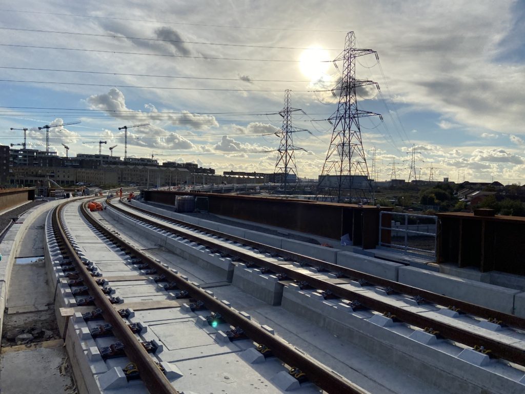
The track infrastructure consists of a twin track extension of the London Overground line beyond Barking station to a new terminus named Barking Riverside. Gospel Oak remains the opposing terminus location for this section of route. The extension continues beyond Barking on a conventional ballasted track system that sits snuggly in the footprint of the existing Tilbury lines for approximately three kilometres. The new lines transition on to an elevated alignment and continue for the final one-and-half kilometres along a viaduct into the new terminus station at Barking Riverside.
RSRG provided the technical expertise to meet this very challenging piece of track engineering and concrete logistics through an integrated design solution for the intermediate layer, slab track system, and switches and crossings. Additionally, the design stage utilised a 4D BIM strategy to manage design and construction risks. The core delivery scope was to undertake the construction of the slab track system on the elevated section as a sub-contractor to the main works contractor Morgan Sindall and VolkerFitzpatrick (MSVF).
For the track system aspects, the design phase was completed between January 2019 and May 2020 and the Construction phase ran from May 2021 and October 2021.
Track system overview
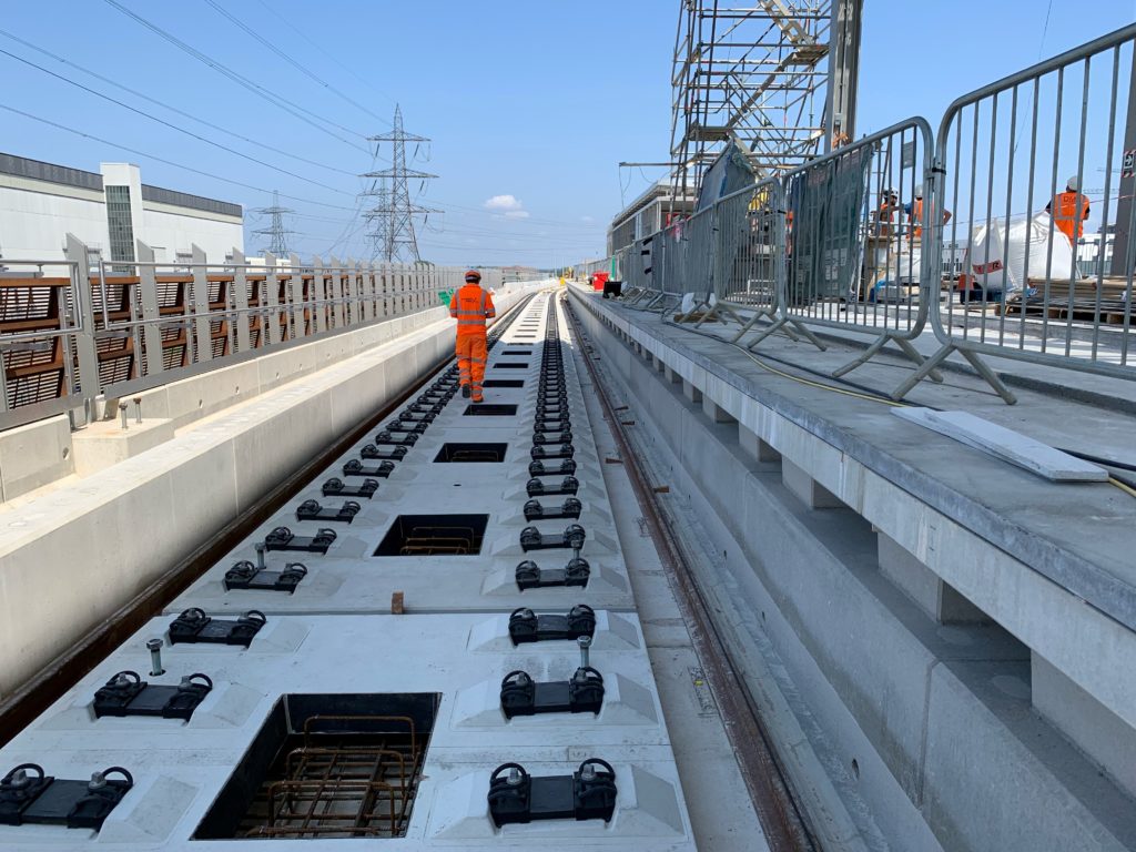
The track system design utilised a precast variant slab track system manufactured by supplier PORR, named Slab Track Austria (STA), incorporating the name of the country where it was first developed and used. The STA system comprises discrete precast reinforced concrete track slabs set on a suitable structural foundation. Once accurately positioned, fixation of the track slabs is achieved with a minimal amount of regular C40/50 self-compacting concrete that is placed though openings in the track slabs and fills the space beneath them.
Adhered to the bottom of the precast slab is an elastomeric rubber granulate sheet to debond the slab from the self-compacting concrete. Shear keys resolve longitudinal and transverse loadings, which are formed when placing the self-compacting concrete within the openings, with two openings being present for a standard slab. The fastening system used was a 300-1 series, provided by Schwihag AG with standard toe load fastening points for 56E1 rail to manage rail stresses and eliminate the need for Rail Expansion Joints. The low toe load section is restrained at each end by full toe load assemblies which provide a robust CWR stress transition zone.
In collaboration with Schwihag AG in response to design work by FCP, the deck end rotation and lateral displacements of the structural design had to be checked and mitigated to limit imparted rail stresses. This was achieved through the selection of an enhanced performance ‘bridge support point’ baseplate and fastening assembly (BSP-FF-B-1) for use under every rail at three support points each side of deck discontinuities.
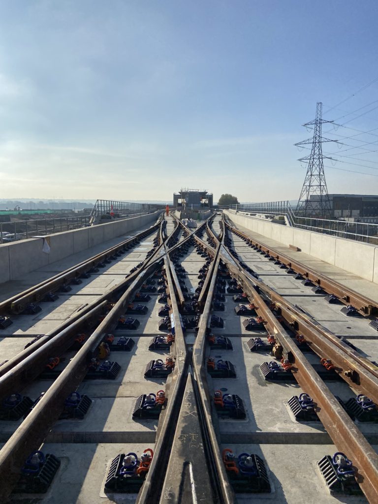
Although switches and crossings upon in-situ slab tracks are well established, for the first time in a UK mainline application, the solution developed for the project also consisted of precast slab track. Thirty-two slab units were provided to cover the whole of the NR56V CV 1:10 scissors crossover. Temporary formworks were set prior to fixing the precast slabs again with a self-compacting concrete (SCC). The rails were fine lined using the internally developed Rhomberg Switch Alignment System (RhoSAS) prior to a secondary grouting exercise, utilising 4,800 litres of proprietary grout, supplied by Fosroc, to fix each fastening into pockets cast into each precast panel.
The ballastless resilient rail fastenings and supports supplied by Schwihag were type DFF SW for the switches and crossings, precisely aligned and designed with the required high elasticity to distribute loads within the track structure. Switch motors and associated signalling, power supply and supplementary equipment are supplied by Voestalpine and Unistar HR type. They were specified to be capable of accommodating the resulting differential movement between the rails and elastic fastenings, and the rigidly fixed track slabs upon which the equipment is mounted.
Geometric design
Several variants of the STA track slabs were used in the project due to geometric constraints, the required fixity into the track supporting structure and requirements arising from the design integration and track bridge interaction. All slab variants have a standardised 2.4m width and 1,435mm nominal track gauge.
There were 91 panel types derived from four categories of slab: (i) standard, for plain line where lengths varied from 2.58m to 5.16m; (ii) transition slabs, where additional fixity is achieved with underlying integrated steel reinforcement elements and the omission of the elastic layer from the slab base. (iii) deck end slabs, where three rows of BSP-FF-B-1 baseplates are integrated at the bridge joint interface and the remaining support points have standard fastenings; and (iv), short deck end type, to suit two specific piers which incorporated thee rows of BSP-FF-B-1 baseplates and additional fixity and no elastic layer on the slab base.
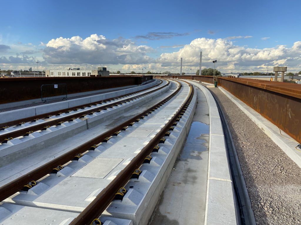
For the Barking Riverside project there are a total of 711 STA slabs including the 32 S&C slabs. The track alignment characteristics consisted of a maximum three percent vertical gradient, the tightest horizontal radius at 220 metres and the highest applied track cant at 100mm. These are currently the highest applied values that the PORR STA system has been installed on in the UK.
Construction methodology
Concrete works preceding the track system installation included the intermediate layer. This is specified primarily to act as a load transferring element into the main bridge structure below, while also serving as a regulating layer to reduce the required volumes of concrete to be placed within the track fixation stage. Linking stirrups were provided to couple the two concrete pour stages to provide a strong and durable mechanical connection for the transfer of loads.
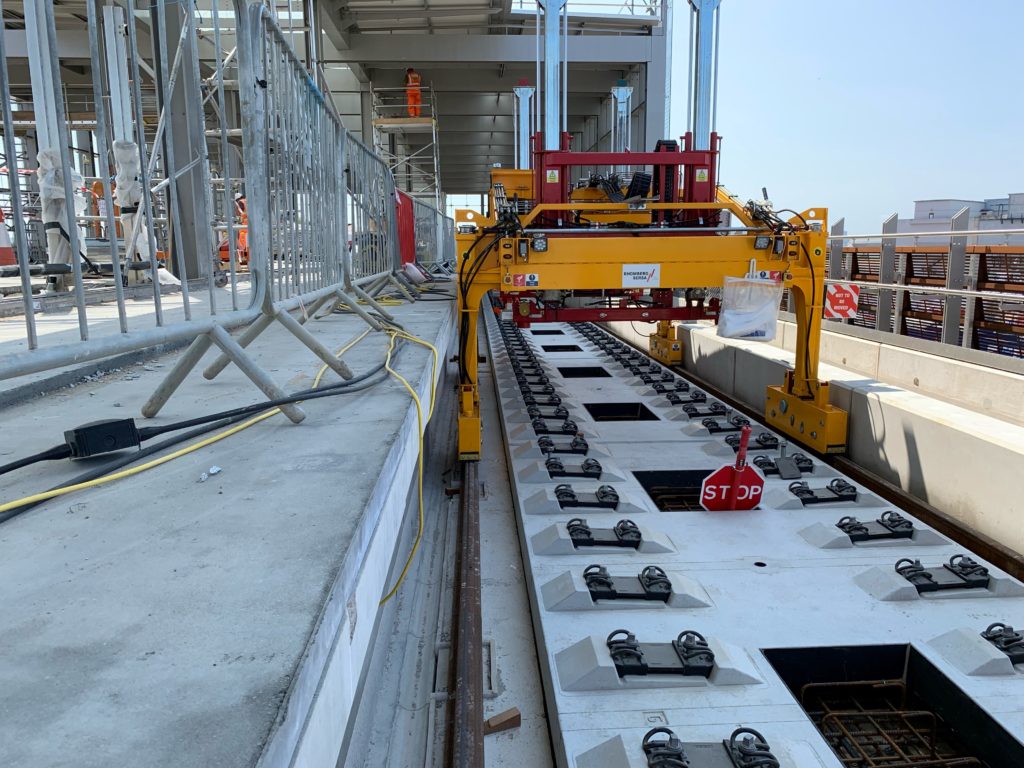
The next stage is to lay out and space the steel reinforcement specified for inclusion within the SCC layer that will fix and support the precast STA slab units. The mobile gantries, developed in partnership with Thomson Engineering, are then used to ‘shuttle’ in the precast STA slabs in the correct sequence. The slabs are then placed and adjusted using threaded spindles, five in number for a standard slab. The tolerance of this process was targeted at +/-10mm but the initial positioning exercise was consistently achieving +/-5mm.
Once the slabs are accurately positioned, the reinforcement is measured and visually checked prior to the formwork being fixed to enclose the space beneath a run of slabs. This is to provide predetermined breaks in the concrete pour. On the project, approximately 1,250 cubic metres of self-compacting concrete was required to provide all of the required fixation. The SCC was provided by Tarmac to site in delivery wagons as 6.5 cubic metre-portions from the batching facility, with each wagon undergoing quality control tests focussing on the material consistency and flow characteristics.
Utilising Tarmac’s logistics management systems, concrete was ordered close to just in time.
From the delivery wagons there were four different logistic modes used to convey and/or place the concrete along the viaduct: (i) mobile concrete pump, several variants of pump were used with a maximum reach up to 47 metres used on the project; (ii) a loading skip attached to a crawler or fixed crane; (iii) a cassette carried under the mobile gantries; and (iv), a wheeled mobile mini-mixer that was able to drive on the intermediate layer.
Technical challenges and developments
As with all track engineering applications, particularly slab track, surveying plays an absolutely critical role in the overall methodology and is the key determinant in the level of geometric quality achieved. The surveyors were tasked with achieving ‘best in class’ tolerances despite the 40mph designed line speed for the new infrastructure, with +/-2mm horizontal and vertical absolute tolerances consistently achieved. This was well inside the required project tolerances: (i) horizontal of +/-6mm; (ii) vertical of +0/-15mm; (iii) cant of +/-5mm; (iv) maximum twist of 4mm; (v) gauge of +/-2mm; (vi) horizontal versine over 10m of 4mm; (vii) vertical versine over 10m of 6mm.
RSRG utilised an innovative Trimble-manufactured GEDO Rail-less Track bar and trolley system in conjunction with Trimble S9 Total Stations. These systems were all supplied by Trimble distributor KOREC and used to undertake the bulk of the surveying positioning work to single millimetre accuracy and also create as-built surveys. Extensive training and on-site support for these solutions were also supplied by KOREC. Multiple sets of equipment allowed referencing and calibrating to reduce the error of individual sets of equipment, and this was done in collaboration with the client surveying team to ensure agreement of obtained results.
RSRG undertook a first of type UK application for ‘rail free’ setting out using the KOREC supplied Trimble GEDO Rail-less system, which resulted in highly accurate positioning of the track slabs. This is where the continuously welded rail is not present at the point of concreting, as the influence of long rail strings behaving differentially to the structural deck is eliminated. (Note, this is only for slab positioning prior to rail installation, and additional work fine-lining was needed immediately prior to the concrete pour). This is new to the UK and will have a significant benefit in the future for installation of the PORR STA system, particularly bridges or viaducts. The GEDO Rail-less Track bars supplied by Trimble sat within the fastenings to act as the reference for the surveying system, instead of the gauge corner typically referenced by trolleys or rail shoe adaptors.
As with the surveying influences, working on a viaduct created other technical challenges. The structure consisted of 31 decks total with nine steel composite decks of 40-metre spans and 22 concrete decks consisting of 2 x 25-metre spans with a fixed central pier. Structural decks naturally expand and contract with variances in temperature, and the steel composite decks were displaying up to 16mm of relative vertical movement over 24 hours for the worst-affected days through the summer prior to the track being installed. To resolve this, three consecutive night pours were implemented while the deck was stable enough to maintain the track alignment and ensure enough concrete strength gain was achieved before the peak variances seen during daylight. With each shift, 120 metres of single track length or approximately 43 cubic metres of concrete was installed within the constrained working hours each night.
Overall, the project was successfully completed by working closely with our client MSVF JV, their client TfL, our partners PORR/FCP and the supply chain. A resilient team effort with strong collaboration among the joint venture and other contractors on site resulted in an efficient overall programme for the track system installation works.