The ongoing £1.2 billion East Coast Main Line (ECML) upgrade is made up of four major projects: the remodelling of the track and supporting infrastructure at King’s Cross to increase capacity, the Stevenage turnback (completed in 2020), power supply upgrades to the whole route and the Werrington grade separation.
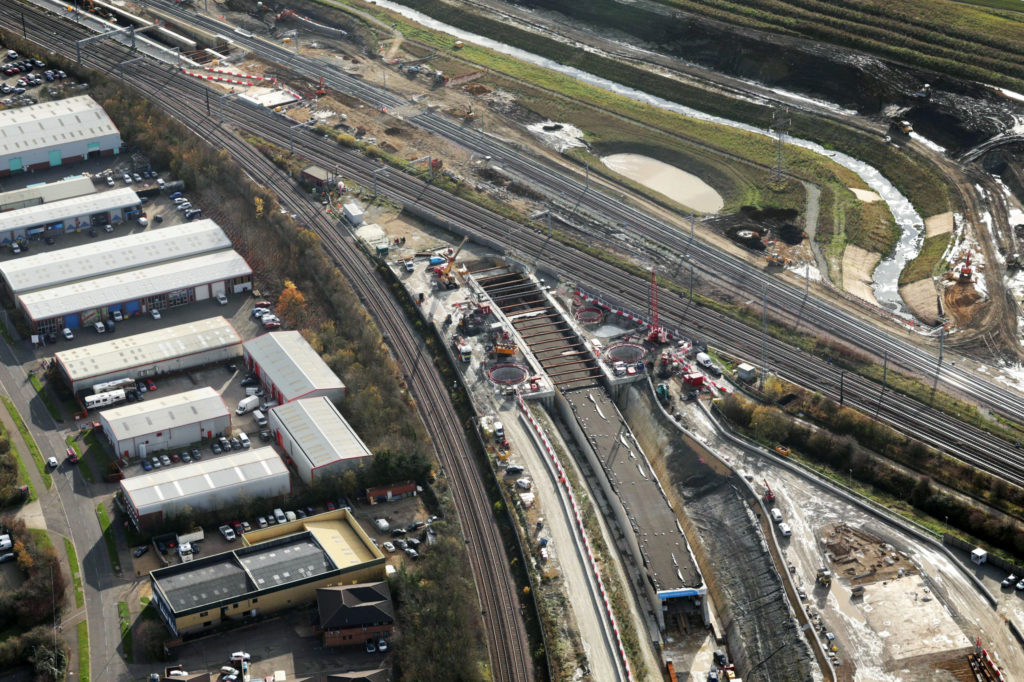
The existing Werrington Junction layout, just north of Peterborough, constrains efforts to increasing the frequency of East Coast Main Line passenger services, as slow freight trains moving onto the Great Northern Great Eastern route (GNGE) need to cross over the two Fast and one Slow ECML lines.
As described in Rail Engineer (see Issue 181, Jan/Feb 2020), Network Rail considered dive-under and flyover options to separate the GNGE services from ECML traffic. But an overbridge was discounted as it would have been a substantial visual intrusion in the flat topography and would also have required diversion of the National Grid’s high-voltage transmission lines.
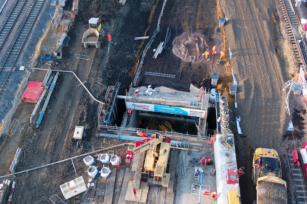
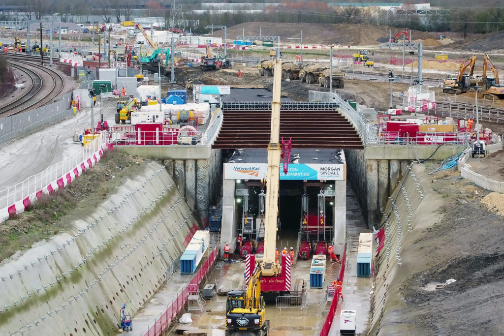
As an alternative to traditional ‘top down and open cut’ options, the chosen innovative solution – which minimised disruption to rail services – was a 750m radius, 155m long portal tunnel constructed alongside the ECML on the new dive-under’s alignment and then jacked into place. Over a nine-day partial closure of much of the ECML between 16-24th January, main contractor Morgan Sindall Infrastructure successfully installed the 11,000t concrete portal, the first time in the UK that a curved structure of this scale has been installed by jacking.
Making sure
The programme constraint here was the nine-day partial closure of the three ECML lines, which governed the planning and methodology for this project. Limited services continued using the Up and Down Stamford lines to bypass the works.
Six days were allocated for the jacking into place of the portal tunnel structure, with permanent way, signalling and earthworks taking place before and after.
Enormous effort went into ensuring the project could be completed on time. The team modelled numerous scenarios and mitigations to minimise risk and ensure contingency measures were in place. Trial jacking was carried out in December to test and prove the systems and method.
At the completion of its installation, Network Rail East Coast route director Paul Rutter said: “Our teams have completed this challenging piece of engineering in a creative way, which also allowed a reduced train service to continue for those who still had to travel. I’m so proud that this project has shown itself to be one which is industry-leading and that our teams have had the opportunity to use this new technique for the first time in the UK on one of the country’s most famous railway lines.”
Design concept
The tender stage design option produced by Network Rail was for a structure to be constructed in sections within a series of disruptive possessions. Morgan Sindall Infrastructure collaborated with Jacked Structures to produce an alternative proposal.
Jacked Structures is a specialist engineering consultancy with unique experience of large jacked structures. Their alternative proposal was for a portal structure running on guide tracks located within preinstalled pilot tunnels, jacked into an open excavation created immediately ahead of it. This was based on their experience of the difficulties, risks and jacking of heavy loads involved in installing traditional box sections. James Thomson of Jacked Structures holds patents for this method whilst Morgan Sindall Infrastructure has a license to use it for the project. This alternative proposal was accepted.
Beginning in 2016, the two companies worked closely with Network Rail’s designers Mott MacDonald and Tony Gee & Partners to develop this unique structure, reflecting the topography, geology and time constraints. In addition to the tunnel itself, the two approaches required substantial retaining structures and soil nailing. The eastern approach also included a substantial reinforced concrete slab on which to construct the portal and provide restraint to the installation jacking forces. All aspects of the project have a 120-year design life.
For this project, the tunnel was constructed on the eastern approach as a portal, with heavy-duty propping at 2/3 height – bracing the portal during installation – with the lower walls cantilevered from it. This concept greatly reduced jacking loads; omitting the floor both reduced weight and removed the high-base frictional loads, often a key consideration in jacked structures.
The slide path for installation was an L-shaped concrete structure. The portal was carried horizontally on multiple hydraulically-linked lift jacks and shoes running on low-friction PTFE slide pads. For lateral guidance during installation around the curve, hydraulically-linked phosphor bronze pads bore against a vertically-positioned steel slide path on each side to keep the portal centralised and resist any out-of-balance ground pressure on the side walls. There was a nominal 65mm clearance to each side.
The slide track beams formed within the guide tunnels bear directly on the very firm mudstone formation and act as strip foundations to the structure, until the in-situ base slab is constructed.
Slide path tunnels
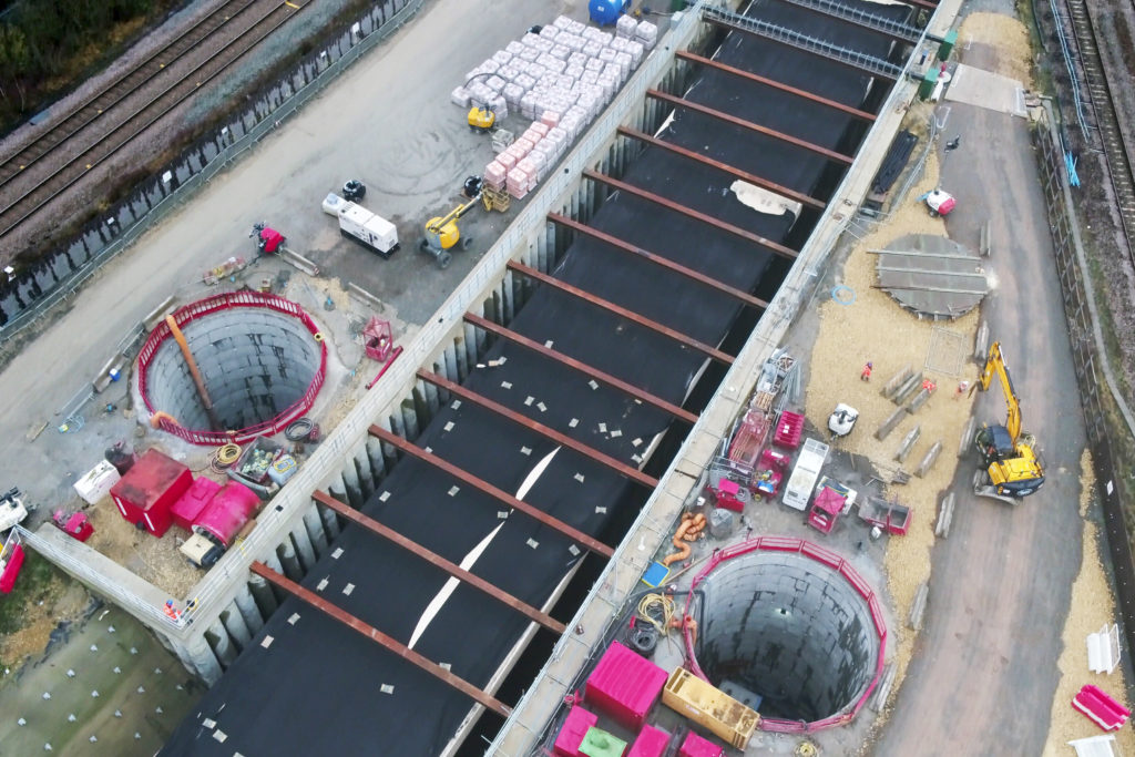
Two parallel tunnels – 168m long and 3.21m in diameter – were driven for the slide path beams. The Earth Pressure Balanced Tunnel Boring Machine was named ‘Chloe and Georgia Whiteman’ after the daughters of Mark Whiteman, a Morgan Sindall Infrastructure engineer working on the project who passed away unexpectedly in 2019.
The tunnels were 7m below the ECML and remote track monitoring was used to demonstrate no disturbance to the tracks above. The machine began work in February 2020, advancing 7m/day and finishing in August 2020.
Works were halted for three weeks at the outset of the Covid-19 national lockdown until appropriate working practices were devised, agreed and implemented. In addition, the site office and welfare arrangements were expanded at this time to provide more space for workers to be separated and to reflect the large number of people then working on site, and in preparation for the three 8-hour shifts during the installation.
Construction numbers
The north ramp was constructed within retaining structures, the first section consisting of a temporary retaining wall of contiguous 18m deep, 900mm diameter rotary-bored piled walls with steel overhead bracing. Beyond this, the formation passes through a steep-sided permanent cutting supported by 900 soil nails – each 8-10m long – and a sprayed concrete facing.
At the north end of the retaining walls, a pre-existing watercourse will cross beneath the trackbed through a pair of 1.8m diameter inverted syphon pipes within two 14m deep, 9m diameter shafts.
The reinforced concrete reaction slab was 750mm thick, supported on 30 bored piles, 1.2m in diameter. The slab included slide path beams to each side linking to those in the twin tunnels. There were also 34 rows of four jack-reaction pockets at 5.4m centres.
A 940m long ramp has been constructed to the south of the tunnel, between the ECML and the slewed Stamford lines. This also acted as the reception pit for recovery of the TBM. Piling for the south ramp consisted of 693 bored contiguous piles – up to 18m in length and 900mm in diameter – as well as 340m of 10-metre sheet piles.
Future drainage will be provided by pumping stations at each end, discharging into watercourses through attenuation features.
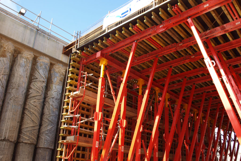
The 155m long, 9.5m wide, 5.1m high and 1m thick portal structure was constructed to a very high quality upon precast base units incorporating jacking and guidance pockets. Bell Formwork used Peri travelling formwork running on VTC tunnel carriages on guide rails.

Once completed, the structure received a spray-applied membrane to the top, with the sides being protected by bituminous waterproofing.
Jacking into place
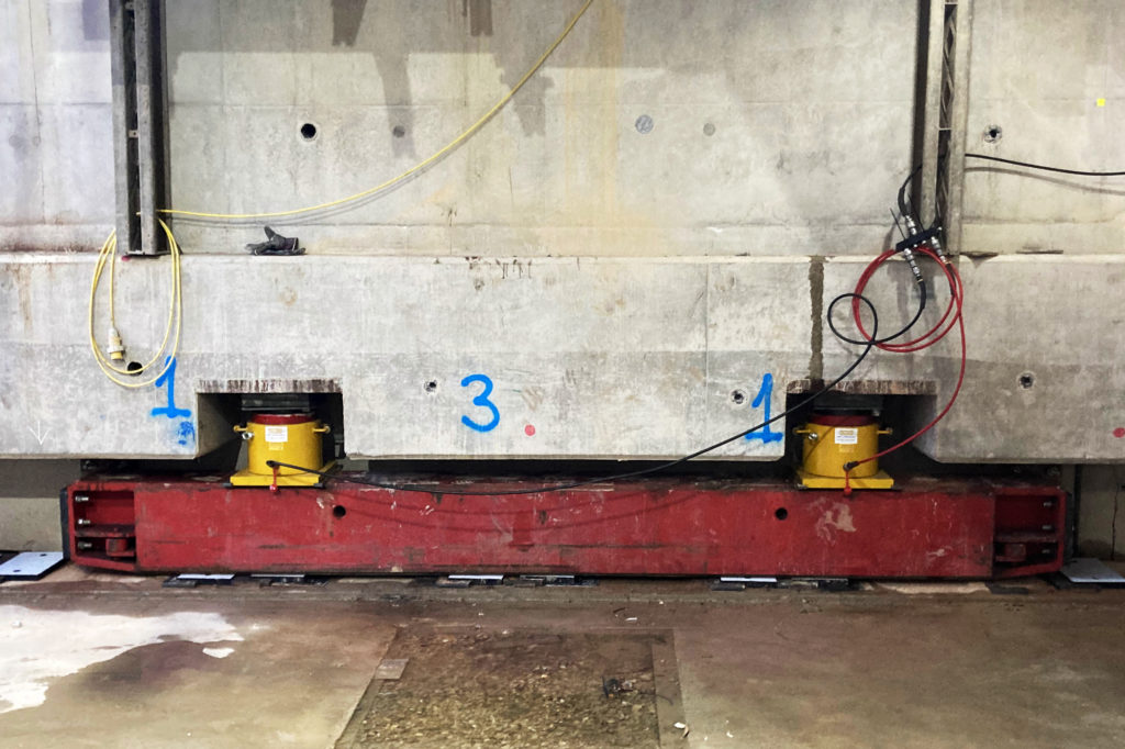
The six-day jacking operation was undertaken by Mammoet on behalf of Morgan Sindall Infrastructure. The structure was lifted off the reaction slab onto skidding beams that ran on PTFE pads on the slide path. Calculations of worst-case scenarios determined a maximum jacking force of 3,600t might be required. The reaction slab and structure were designed around four installed jacks that could provide up to 5,000t.
Mammoet’s jacks are normally used vertically to raise offshore modules, but here were used horizontally. They were attached to the portal’s thrust slab, a section of floor slab between the portal feet, and their self-weight slung from a temporary overhead frame. The jacks bore against relocatable steel reaction frames set into pockets within the jacking slab and were extended in 2.7m strokes. 2.7m extension pieces were placed after a full jack stroke to enable a total length of 5.4m to be installed before moving the reaction system to the next available jacking pocket. 34 sets of four pockets were provided. Test jacking took place in December, using the first three sets, giving 13.5m of initial travel.
The worst-case scenario assumed that the ground would slump against the sides of the portal as it was jacked through. In the event, the stiff ground did not slump and the maximum jacking force used was just 900t.
The jacking sequence was as follows:
- Hydraulic crawler crane running on base slab, lifts in jack reaction frames into pockets in slab.
- Hydraulic jacks push against these to move the portal forward by 2.7m.
- Crane lifts in intermediate jack extension frames.
- Hydraulic jacks push against these to move the portal forward by a further 2.7m.
- At the front, side cutters fitted to the portal cut the ground profile and excavators cleared the earth for the portal to be pushed forward. The cutter overbreak for this was just 50mm wider than the portal itself. The excavators also carefully broke open the tops of the two circular guide tunnels to reveal the two slide paths inside.
- Spoil loaded and taken away by a fleet of dump trucks, in total approximately [16,000m3].
- Once the jacking was complete, pea gravel was poured between the portal and the excavation sides and subsequently further filled and sealed with cementitious grout.
The timeline of the nine-day partial closure was:
- From 21:00, Friday 15th January: bidirectional signalling arrangements set up on Stamford lines and temporary works to GNGE so that signalling was not affected when track removed.
- Saturday 16th January: signalling taken out and disconnected, tracks removed and OLE lifted. Bulk excavation and jacking began at 13:45.
- Sunday-Thursday 17-21st January: bulk excavation continued throughout portal jacking. Push completed at 02:30 and jacks released at 22:00 on 21st January.
- Friday 22-24th January: reinstate signalling, permanent way and OLE.
- 04:55 Saturday 25th January: handback in time for full passenger services to resume.
Over 24,000 hours were worked over the nine days, with no accidents or lost time.
Completing the works
The project has already delivered substantial elements of permanent way, drainage, structures and other works, but much remains to be completed.
The floor slab inside the tunnel will be constructed tied into the side walls, becoming the ground-bearing element of the structure. This will include a vertical curve at the east end as the track alignment rises up through the cutting to form the north ramp.
Ballasting and installation of 8,000m of permanent way will follow. The junction with the GNGE tracks at the north end (Glinton Junction) will be installed in the autumn and with the Stamford lines at the south end in June.
The life-expired Werrington interlocking will be upgraded to a computer-based interlocking which will be carried out during a three-day possession in June, the same weekend at the King’s Cross commissioning works.
The target approval of the new works by the Office of Rail and Road is at the end of October. The new junction will be reflected in the enhanced ECML services of the 2022 passenger timetable improvements, but is expected to be used by freight trains by November.
The long-term effects of Covid on rail travel are unknown, but the business case for this project was based on long-distance traffic which is less affected than shorter commuter journeys. The project will be a key component in increasing ECML capacity from six to eight long-distance high-speed services each hour.
This project has been a record-breaking application of this patented method of constructing a dive-under and is one that may well be replicated by Network Rail in the future for similar projects where ground conditions are appropriate.