

In Issue 195 (March/April 2022) Rail Engineer reported on a February 2022 Institution of Mechanical Engineers’ seminar which examined the factors that might lead to rolling stock cracks and fractures. The article presented two case studies showing how these issues had affected two fleets. The second part of the article, presented here, focusses on the Intercity Express Trains which were suddenly withdrawn from service in May 2021. With the passage of time since the seminar there are updates to the story, particularly with the publication of ORR’s final report into its investigation.
A case study of the Class 80X Cracked Yaw Damper/Anti-Roll Bar (ARB) Brackets and Vehicle Lifting Pads issue, was presented by Andrew Skinner, head of engineering, at Great Western Railway (GWR).
Background
The Class 80X fleet currently numbers over 1200 vehicles, operated by First Group (GWR, Trans Pennine Express, Hull Trains & Lumo) and government owned London North-Eastern Railway (LNER). The trains were manufactured by Hitachi and are owned by Agility Trains, Angel Trains, Beacon Rail and Eversholt Rail. Similar trains are on order for East Midlands Railway and Avanti. This case study focused on the GWR sets (just over 600 vehicles) which are owned by Agility Trains & Eversholt Rail and maintained by Hitachi which is also the Entity in Charge of Maintenance (ECM).
Andrew explained that the Railways and Other Guided Transport Systems (Safety) Regulations 2006 (as amended) requires a transport operator to have a safety management system. Specifically, Regulation 5(1)(d) requires an operator ensures “…the control of all categories of risk including new or existing risks associated with the operation in question…”, and, as the operator, GWR must work with stakeholders and partners to assess, control, and manage new risk, but is always the responsible party.
The trains are equipped with both inside frame and outside frame bogies. They have motor and trailer bogies and there are differences in mass between different vehicles in the formation. The photo overleaf shows an inside frame bogie on an intermediate vehicle with all the key components affected by this issue labelled.
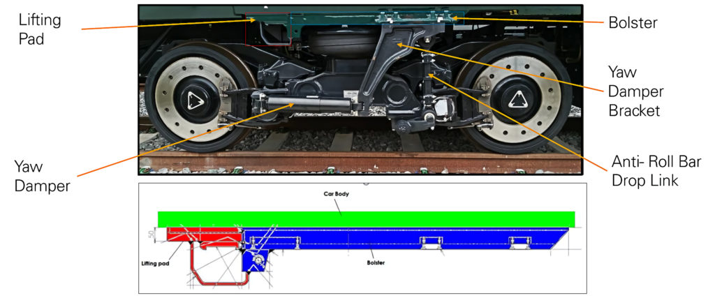
There were early signs of a problem when marks were discovered on a bolster above the yaw damper bracket mounting, initially thought to be score marks left after trimming some bodyside vinyls. The marks polished out and were repainted, but the marks returned; clearly a crack, confirmed after NDT (dye penetrant). A special check was initiated, and eight out of 93 units were found to be affected. 800013 exhibited a different crack. An investigation started and investigators observed the subtle differences in the arrangements.
The heaviest vehicles had the yaw damper bracket bolted to the body bolster and then the ARB top link was bolted to the yaw damper bracket, whereas on driving trailer vehicles, which are lighter, the yaw damper bracket and the ARB top link was secured separately, with six fastenings compared with four on the intermediate vehicle. Andrew explained that the nature of the forces reacted by the vehicle bolster, horizontal for the yaw damper and vertical for the ARB, are both cyclic in nature and alternating in direction and intensity. This issue, which had been notified to all other operators, was believed to be fatigue in the weld between body and bolster. Structural analysis to support a risk assessment had shown the vehicles to be safe to operate while an inspection regime was put in place and interim/permanent repair schemes were developed. All in all, the issue was under control.
Discovery
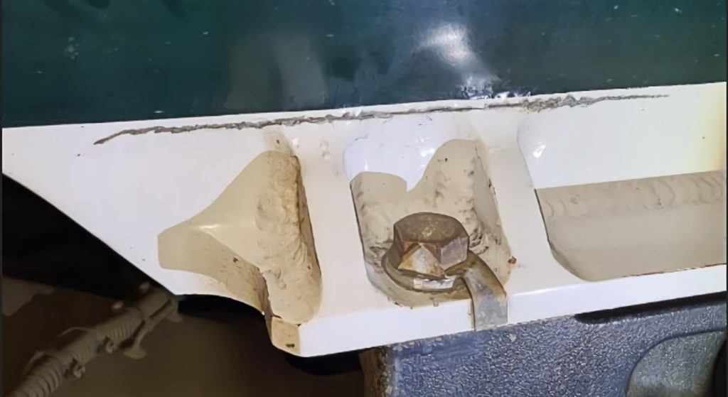
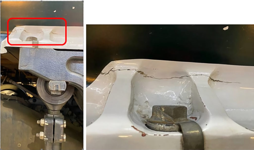
Then, on Saturday 8 May 2021, cracks were visually detected in parent metal at the other end of the bolster around the lifting pad. The ECM took the decision to withdraw the affected fleet, due to the risk that a large piece of metal could become detached and injure someone alongside the train or even derail it. This left only three units serviceable. Discussions started between the partners and stakeholders, with GWR the responsible transport undertaking. Andrew said that there was an extra challenge as it was a weekend, but everyone took a deep breath and started to talk about what actions to take. The defects were puzzling as there is only very limited operational loading in the lifting pad, and a working hypothesis was formed that this was stress corrosion cracking (SCC). Part of the initial challenge was the partners’ limited knowledge of SCC (see panel).
A number of cross industry peer groups were set up with technical reviews led by the ECM and supported by an independent third party. It was rapidly established that the lifting pad was manufactured from grade A7204 (7000 series) aluminium plate which is prone to SCC. As already stated, this area is not highly stressed in service but there were residual stresses as the area had not been stress relieved after welding during manufacture, and the area was exposed to corrosive atmospheres with the UK’s endemic moisture and rainfall, as well as along the sea wall at Dawlish (UK seawater has a salinity of just 3.5%). The SCC boxes were ticked. Once the issue had been understood, at least in part, a risk assessment was carried out and an inspection regime was put in place, which allowed the overwhelming majority of the fleet to be returned to service. Later a weld repair for the lifting pad was agreed.
Containment
With the fleet back in service, there was breathing space to develop permanent solutions. A lifting pad was removed, and bolster welds were excavated and subject to metallographic inspection. To aid inspection, low and high frequency eddy current testing with bespoke probes and procedures were developed for this configuration.
The next question was “where else might be affected by SCC?” Hitachi carried out a review and determined the risk areas to be where all the following factors were present: 7000 series aluminium used, plate thickness greater than 12mm, plate edges cut or machined close to a weld bead (i.e., where the distance from the edge of the weld bead is less than the plate thickness), and where the cut or machined surface had no stress relief process applied. The areas affected were identified and, on inspection, a crack was found in a coupler support bracket plate with a very low risk of catastrophic failure. Cracks were also found in yaw damper bracket stiffeners, and these required temporary weld repair before service.
Finite element analyses of the lifting pad and yaw damper/ARB area were produced with appropriate welds omitted to simulate cracks. This informed a HAZID/risk assessment and helped the development of control measures. For the lifting pad, a maximum of two cracked faces was allowed. For the yaw damper/ARB bolster, visually identified cracks less than 200mm were allowed. These checks were carried out daily by maintainers. Non-destructive testing of known cracked yaw damper and ARB bolsters was carried out every 30 days with the same length limit. The inspection process generated a great deal of data about the locations and lengths of cracks.
It was also necessary to address the labour and time intensive daily checks. With information coming in about over 2400 locations daily, and just for the GWR fleet, managing it all was unsustainable. Further FEA analysis demonstrated that with specific welds intact there was no risk of lifting pad detachment. This allowed the check to be moved to 36 days with any new cracks having to be repaired in the following 36 days.
The yaw damper bracket/bolster crack propagation rate had been monitored over a period of months and had been calculated on both a mileage and calendar basis. From examination of the worst cases, it was shown that a modest shortening of the allowable limit from 200mm to 180mm would allow this inspection frequency also to be extended to 36 days.
Permanent bolster repair
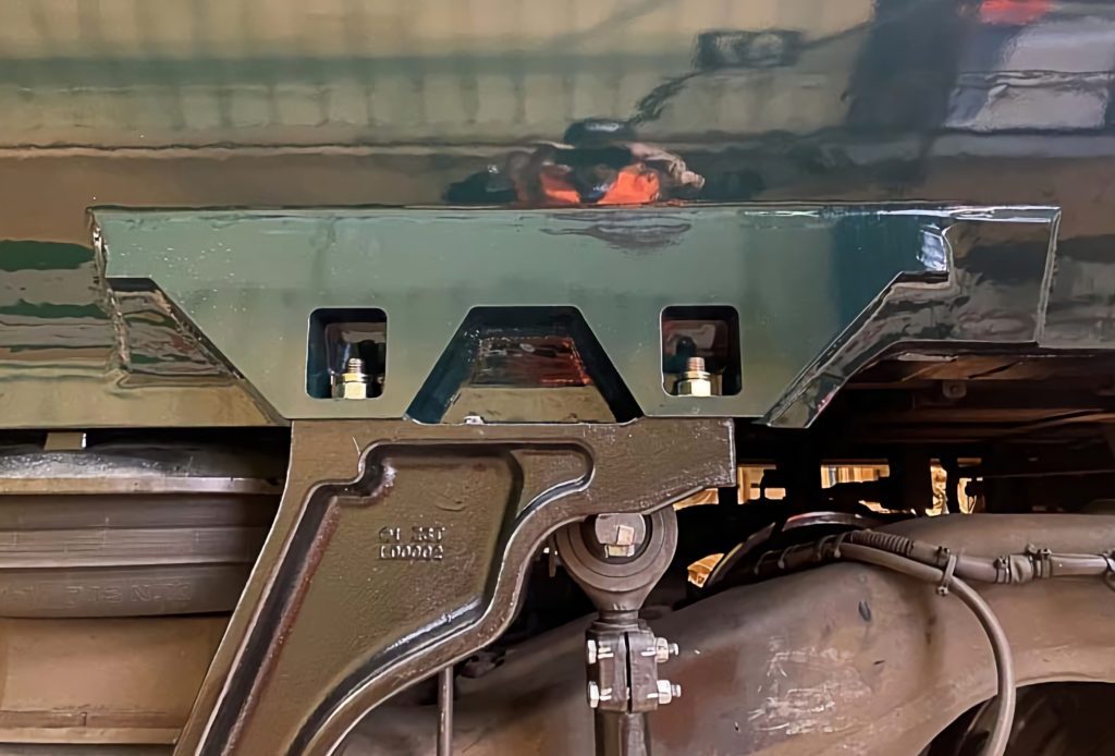
With the issue being managed, Andrew reported that work is under way to develop permanent repairs. Through continued technical research and development as well as stakeholder dialogue it had been established that it is difficult to weld to the root of the body/bolster interface and consequently full weld fusion would be difficult to achieve. Moreover, during testing with strain gauges over representative routes there were occasions where the loads on both the yaw damper bracket and the ARB drop link exceeded the design assumptions affecting the fatigue life. Both factors informed the development of new parts that would be welded onto the existing carbodies.
Different solutions are required on different vehicles which have all been strain gauge tested. One of the designs is illustrated.
Andrew closed with wise words for people leading or otherwise involved with such crises: always remain curious; if it’s a new problem, read up on it; don’t panic; work and communicate with peer groups across stakeholders; remember ROGS – the requirement to control new and existing risks; use experts and independent review to verify proposals; take things a step at a time; model and test where appropriate; keep talking, freely share with others & keep the commercial folk out of the room; and, finally, make arrangements to keep the day job going.
ORR review
Since the seminar, the ORR has published its final report into its investigation of the cracks on the class 80X Intercity Express Trains. It also reviewed Hitachi’s investigation into cracks which occurred on the different designs of bolsters on classes 385 (ScotRail) and 395 (South Eastern Trains), and SCC on class 395 obstacle deflector brackets which is being managed using similar approaches to those being employed on the Intercity Express trains.
The report aimed to: (i) Determine the root cause of the cracking at the lifting end of the bolster and around the yaw damper/anti-roll bar connections to the body; (ii) Examine how the industry identified the problem, assessed the safety risk, withdrew the trains from service, and later reintroduced them; and (iii) identify areas for improvement.
This short note covers just points one and three as the second point is outlined in the case study above.
Fatigue cracking
ORR reported that Hitachi’s technical review of the fatigue cracking at the yaw damper body mount had concluded that: (i) fatigue cracking was caused by the area of the bolster subject to yaw damper and ARB loads being greater than allowed for in the original design; (ii) there was evidence of poor fusion in the weld between the bolster and the car body which was one of the causes of the cracking; and (iii) Hitachi has identified that the geometry of the components prior to welding contributed to the poor weld fusion identified above.
ORR reported that: “the applicable standards define the accelerations to be taken into account when designing rolling stock but do not directly mandate the strength of components, which will depend on the individual vehicle design. Other rolling stock built in conformance to these standards has not presented similar problems. It is not yet known for certain the reason for the in-service fatigue loads on the rolling stock to exceed those Hitachi derived from the standard. Potential factors that have been suggested include wheel wear and track specification.
“Hitachi’s testing has identified a difference in loads arising from new and worn wheel profiles. Further work needs to be undertaken to evaluate whether the characteristics of track on the routes over which Class 80X rolling stock operates differ from those assumed by the standards. There is no evidence that the condition of the track on the routes was anything other than compliant with the applicable standards and therefore conformed to its specification.”
ORR Recommended that the “industry should conduct further work to identify the reasons for the higher levels of fatigue loading experienced by [this] rolling stock. Since the Hitachi design complied with the applicable industry standards, the industry as a whole should evaluate whether the applicable standards take into account the loads arising from operation on the rail network in Great Britain.”
Stress corrosion cracking
ORR’s report identified that the three factors, all of which have to be present to cause the cracks, was the choice of a 7000 series aluminium alloy, the presence of sodium chlorides in the typical UK atmosphere, and residual stress arising from the welding of the lifting plates which had not been stress relieved.
ORR recommended that designers of rolling stock should understand the risk posed by SCC and evaluate it if proposing 7000 series aluminium components. Its recommendations include:
- Avoiding its use on components that are likely to be exposed to mildly corrosive atmospheres when residual weld stresses are present.
- Where used, aluminium plates less than 10mm thick are preferable.
- Where used, the exposed grain structure ends of extrusions should be protected using a technique such as welding.
- Avoiding residual weld stresses.
- Employing surface protection such as weld buttering on all components that present a risk of SCC.
Avoiding the use of paint as a protective measure. - Exploring residual stress relieving methods.
ORR’s review concluded: “We have not identified any potential breach of health and safety law as the train operators have demonstrated effective management of risks throughout the process through working closely with Hitachi and other organisations.” ORR plans to use the knowledge from this review to inform their continued engagement with all the parties.
Rail Engineer comment on the ORR report
Both GWR and the ORR say that the loads experienced by the yaw damper/anti-roll bar mounting were higher than had been assumed in the design and verified during testing. ORR also reported an issue with weld quality but made no comment about how much each issue contributed to the cracking.
The key standard, EN 12663 offers three ways to assess the loads: (i) dynamic modelling, (ii) measured track quality over the intended or similar route, or (iii) empirical data. It offers some basic values that can be used for the third option, suggesting strongly that these might be used if nothing better is available.
Rail Engineer notes that the September 2021 ORR interim report stated: “The train design and joining methodology were subject to computer modelling and analysis, and fatigue load testing of a sacrificial car body. Input loads were calculated using track data received by Hitachi as a part of contractual documentation.” However, the source of this data is not clear. Possibly it could have been the specification for assessment of ride comfort or the more comprehensive data from Network Rail’s New Measurement Train (NMT). Was the more extensive NMT data asked for and if, so were they made available?
This issue is likely to be central to the commercial settlement negotiations between Hitachi and its customers.
It was also surprising to see the statement that “loads were somewhat higher than had been assumed for the design”. Given that the issue affects all the trains Hitachi has supplied to UK, perhaps there is something systemic about their understanding of the load environment, the use of that information in the design, the quality of construction, or a combination of all three.
ORR recommended: “Since the Hitachi design complied with the applicable industry standards, the industry as a whole should evaluate whether the applicable standards take into account the loads arising from operation on the rail network in Great Britain.”
It was not clear to Rail Engineer why the ORR should consider that the standard (presumably EN12663) needs to be reviewed, so we put this point to the ORR. ORR’s Giles Turner commented: “From the material we considered, we were satisfied that the requirements of the applicable legislation were met and the statutory process in turn confirmed that the appropriate standards were complied with. An independent accredited body reviewed the designers’ work and there has been no suggestion of shortcomings in this process. However, the design nonetheless resulted in fatigue cracking. Therefore, quite simply, we recommend that the industry review the standard.”
Turning to stress corrosion cracking, this was not something that had been a significant issue in GB rail and led many engineers to resort to textbooks. What has become clear is that the choice of material, type and thickness; the prevailing environment; and how it is used (e.g., if the construction method led to residual stress in the structure), were all factors that caused the SCC and eliminating any one of these would have eliminated the risk. The atmospheric environment is a fact of life, any examination of the routes these trains operate would have identified the saline atmosphere even without considering the impact of damp, rain, and salt on roads. The other two issues were both in the hands of the supplier.
Aside from the cost already incurred – service disruption, inspection and temporary repairs – there is no doubt that this will be an expensive rectification programme, likely to be in excess of £100 million.
STRESS CORROSION CRACKING – FROM ORR REPORT:
Stress Corrosion Cracking (SCC) is a mechanism whereby cracks develop in susceptible materials when they are exposed to a specific corrosive environment while subject to mechanical stress. The stresses involved in SCC are usually significantly lower than those involved in mechanisms where the stress alone is sufficient to cause cracking, thus making certain materials susceptible to cracking under conditions where the mechanical design would otherwise be sufficient to prevent it. SCC has been likened to the fire triangle where fuel, heat, and oxygen must all be present for combustion to take place; if any of the three elements are missing then there is no fire. In the case of SCC, the three elements are:
(a) the susceptibility of the material
(b) the specific corrosive environment to which the material is susceptible
(c) mechanical stress in the material