

In issue 190 we described HS2’s 3.37km Colne Valley Viaduct. Immediately to the north of this will be another of the project’s mammoth structures, the twin 16km long, 9.1 metre diameter Chiltern Tunnels, passing beneath Chalfont St Peter, Chalfont St Giles, Amersham and Little Missenden. These will be the longest of the 130km of tunnels to be built during HS2 Phase 1. These are currently being built by Align, a joint venture formed of three international infrastructure companies: Bouygues Travaux Publics, Sir Robert McAlpine, and VolkerFitzpatrick.
The tunnel alignment was based on extensive ground investigation during the early preparatory works for HS2 and was designed to pass through the chalk strata, up to 90 metres deep, beneath the Chiltern Hills. Designed specifically for the ‘chalk with flints’ that they will encounter, the two identical Tunnel Boring Machines (TBM) will dig the tunnels for north and southbound trains.
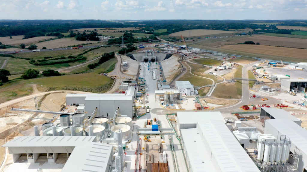
On site manufacture of tunnel lining segments
Align’s Chalfont Lane site will be the biggest construction site on the HS2 project and includes pre-casting factories for both the Chiltern Tunnels and Colne Valley Viaduct. David Andrews, the Tunnel Precast Manager, explained that many projects set up fabrication facilities in sub-optimal existing buildings that do not usually have the space required for the scope of works. For the huge scale of this project, Align, along with their shed supplier, Caunton Engineering, have designed and built a huge factory, bespoke to the needs of the production, storage and logistics activities of the production operations. The large-scale U-shaped segment factory is located alongside the viaduct precast factory but is operated independently.
Concrete for the production facility is batched on site in a large-scale, purpose-built batching plant, positioned between the two factories. Tarmac are Align’s concrete supply partner for this project, selected on their track record of supporting complex infrastructure projects of this scale. Segments use high-grade stainless steel-fibre reinforcement which offers greater ductility and cost savings for reinforcement work. Where cross passages and shafts will be cut through the rings, and in fault zones, segments also include steel rebar reinforcement. Each of the ring’s seven segments are slightly different to allow them to tightly lock together and their orientation can be adjusted during installation to allow slight curvature or corrections.
The factory includes two semi-automated production lines, with each line containing 49 segment moulds (seven complete rings) cast in a predetermined order. Each factory is planned to cast 49 segments in each shift, or about one every 11 minutes. At two metres width per ring of seven segments, this equates to the needs of a day’s tunnelling.
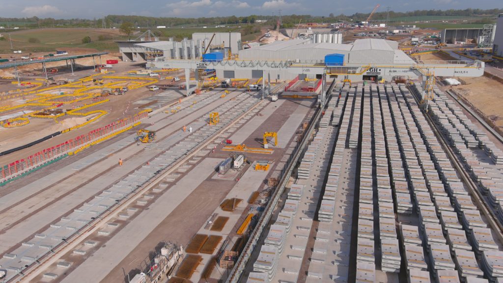
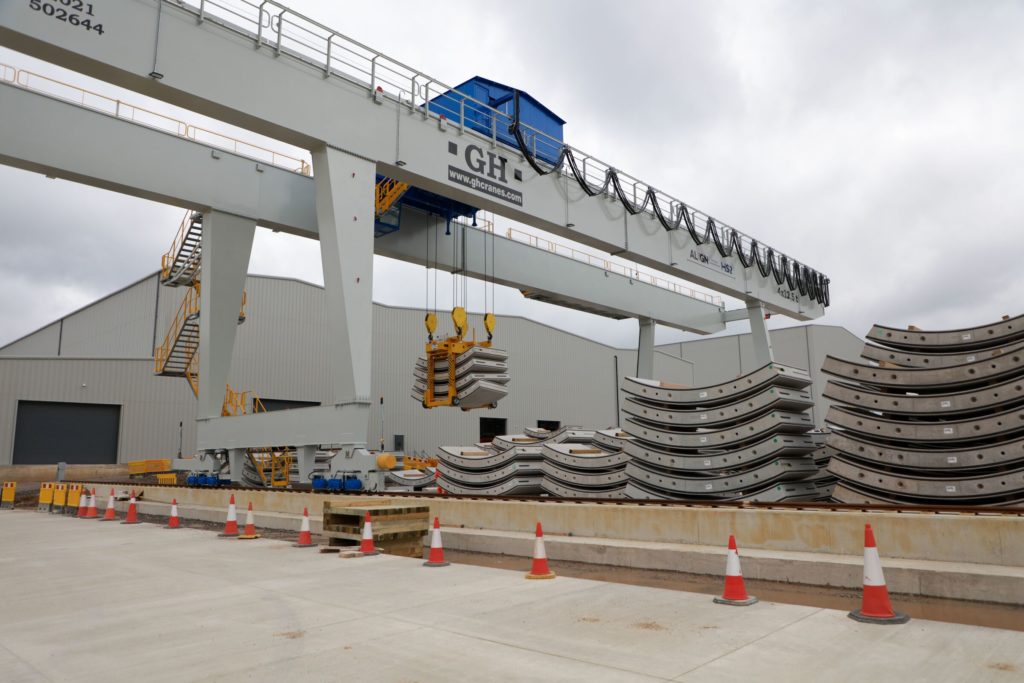
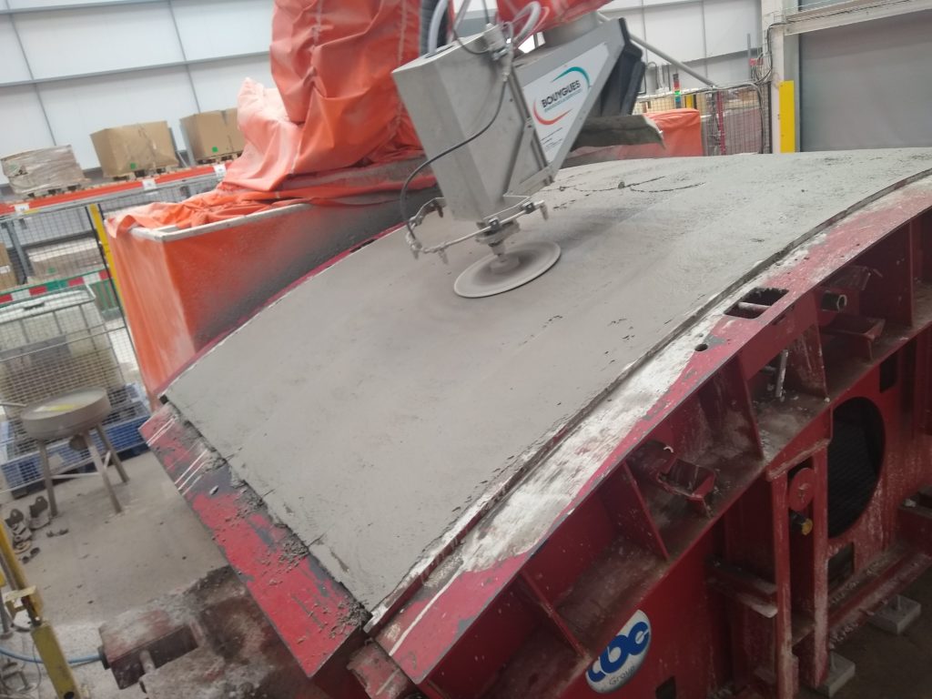
Robots are used to undertake the repetitive tasks of cleaning the segment moulds prior to the concrete being added and for the final finishing of the concrete surface, minimising human intervention, and improving the quality and consistency of the final product. Segments are then cured in an oven area for six to seven hours. On completion of curing, the segments are stored in adjacent pre-storage carousels in stacks of four and three, to continue the curing process. The next day, the stacks are transferred out to the external storage yard, beneath large travelling gantries, to await their journey into the tunnel. Production started three months ahead of the first TBM launch in May, in order to build up a stock of 1,900 rings, ensuring that the TBMs will never be short of segments to place.
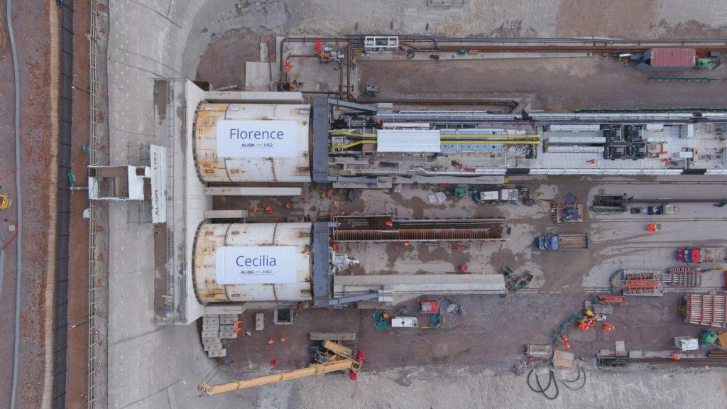
Florence and Cecilia
TBMs are always designed to cope with the geology and hydrology of the tunnel alignment. The TBMs here were specified by Align, working closely with manufacturer Herrenknecht to design the two identical 170-metre-long machines specifically for the Chiltern Tunnels. Proactive collaboration led to the inclusion of innovative features into the design, facilitated by Align’s Underground Construction Director, Didier Jacques’s, long experience in tunnelling and work with Herrenknecht on previous projects.
Built, assembled and tested at its factory in south-west Germany, these were transported to site in more than 300 shipments during 2020, before being reassembled, re-tested and commissioned at the tunnel’s south portal launch site. The six different gantries for each TBM were assembled on site and then transported to the south portal TBM Slab, where they run on rails until they enter the tunnel. Once inside the tunnel the TBMs run on rollers on the inner side of the tunnel. Herrenknecht’s engineers will remain on site for some time to ensure that all systems are working correctly and to learn from its performance in service.
Traditionally, TBMs are given women’s names in honour of Saint Barbara, the patron saint of miners. Here they are named Florence and Cecilia, suggested by students at the local Meadow High School and The Chalfonts Community College and chosen after a public vote. The names celebrate Florence Nightingale and the astronomer and astrophysicist, Cecilia Payne-Gaposchkin.
Shannon O’Keeffe, Align’s TBM Manager, described the layout and functions of the underground factory that make up the TBM. Each is controlled by a crew of 17, led by the shift foreman, the TBM pilot and TBM engineer, supported by miners and the mechanical / electrical teams. An additional crew supports them, with another 30 people involved in bringing segments down the tunnel, grouting and other support roles. These are a mix of Align employees and specialist tunnel labour supplied by TG Tunnelling.
The TBM is made up of six back-up gantries, and the shield which consists of the cutterhead, ring building area and slurry circuit. The TBMs are a variable density type which constantly maintains pressure to the ground whilst excavating using slurry water. A manlock behind the cutter head in the shield allows for access into the pressurised head for maintenance and repair. The ground is excavated by the rotating cutterhead and the excavated material is transported through a screw conveyor, which then discharges into a slurry mixing box where additional water can be added to assist in pumping the slurry and excavated material back to the portal, at up to 1250m3/hr. The sound of excavated flint rattling in the discharge piping reminds the crew that the flow is working and the TBM is mining.
As with traditional TBMs, each ring is excavated and then installed sequentially. The segment erector picks each of the seven segments that form a tunnel ring from the segment feeder, rotates them to the required orientation and installs them into position against the previous ring. Currently, this installation operation is manually controlled but testing on an innovative automatic system is underway. An additional part of this new technology is the ability to continuously excavate and install segments as TBMs advance forward. This is achieved by adjusting the thrust of the TBM, pushing more or less on different segments in each ring thereby allowing a segment to be installed as the TBMs continue to move forward without affecting the tunnel alignment. As the TBMs advance, the annulus behind the rings is sealed with cementitious grout batched on the TBM.
Behind the control room on the TBM gantries are the hydraulic pumps, electrical switches, transformers, and the batching plant as well as welfare facilities for the tunnel teams. There are also two refuge chambers which can be operated in case of any emergency. These can independently provide breathable air for up to 24 hours if the crew cannot evacuate the TBM or tunnel.
Each of the 8.5 tonne segments are brought into the tunnel by multi-service vehicles. These are double cabbed as they cannot be turned within the tunnel and allows for the operator to always face the direction of driving. The vehicles drive into the rear of the TBM and segments are unloaded by the quick unloader, then lifted by the segment crane onto the segment feeder to the installation area. The stacks of these include timber packings. To avoid the risk of human entry into the moving and lifting of segments, another robotic unit removes these automatically, this being one of the most impressive innovations applied to these TBM. This same robotic arm then also inserts the jointing dowels into the segments before they are placed onto the feeder ready for installation.
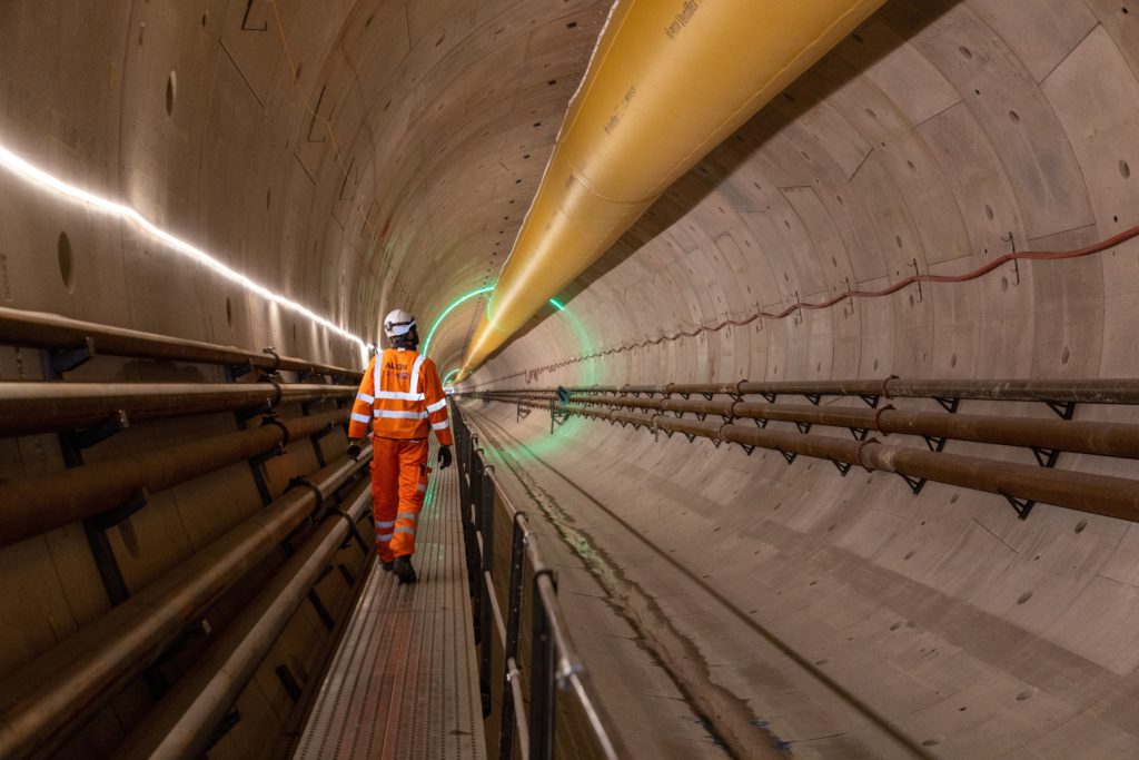
To provide a roadway for the multi-service vehicles, and as the base for future slab track, the curved bottom of the tunnels is filled with concrete to form a flat surface. A moveable steel bridge unit is used above the wet concrete enabling vehicles to drive over to feed the TBM. The TBMs are powered by a 22kV power supply, fed from the National Grid and sourced from renewable energy only. As the TBM proceeds, every 300 metres a new section of power feeder cable is inserted, along with extensions to cooling water, slurry, ventilation, communication and other supporting utilities.
Florence launched in May with Cecilia following in June. Despite starting second, Cecilia will run slightly faster, aided by geological data and experience fed back from Florence, meaning that both machines are due to break through at the north portal around the same time. Although relatively early into the programme, the teams have already achieved a production peak of 24 metres per day, achieved whilst passing under the M25 where the team were keen to get beyond the highway’s zone of influence as quickly as possible. This faster operation, whilst impressive, can result in greater wear and tear, so the teams are planning an average 15 metres per day for the remainder of the project.
Using tunnel slurry to form new chalk grassland
Much of the 3 million m3 of chalk excavated from the tunnels will be used for landscaping at the south portal site once construction is complete. The ‘Colne Valley Western Slopes’ project will see the construction site transformed into chalk grassland which is lime-rich, thin soil, low in nutrients. This new grassland will attract a huge variety of plants: up to 40 species per square metre including some of the UK’s rarest orchids and invertebrates. The new habitat of 127ha will provide a huge increase on the existing 700ha within the Chilterns AONB.
Excavated chalk is being pumped from the tunnels as a slurry. First, this is passed through a trommel screen to collect granular material leaving suspended particles and water. This is then put through filter presses that squeeze out water, leaving chalk cake. The water is returned to the tunnel for further uses, and the solids stored in stockpiles.
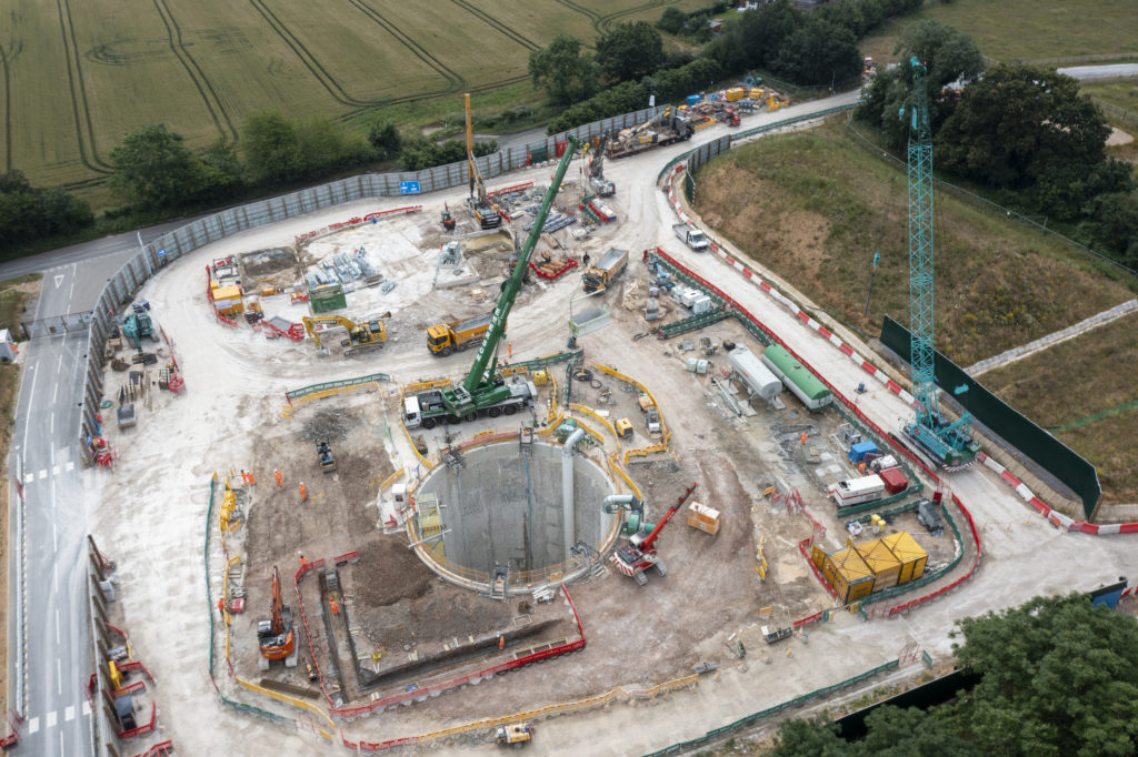
Vent shafts
Every 2-3km along the tunnel, a vent shaft will be constructed. These will provide for air movement in the tunnel, smoke extraction in the event of fire, as well as to provide maintenance and emergency service access.
The first of these is under construction at Chalfont St Peter. It is of 17 metres diameter and 67 metres deep. The shaft’s concrete walls are formed of 16 diaphragm panels. When complete it will include a headhouse inspired by nearby agricultural architecture to help it fit into the surrounding landscape. The shaft is located centrally between the two tunnels and will contain the fans and emergency access stairs. The TBMs are expected to pass it during early 2022.
It will be 2024 before these tunnels are complete, but already the massive scale of the project and the innovative aspects of its design and construction are clear, setting standards for future projects.
Lead photo: Ring sections outside the precast factory at the Chilterns Tunnel South Portal.