

In 2019, a network of universities and industry partners concerned with railway research was formed. The UK Rail Research and Innovation Network (UKRRIN) was built on three Centres of Excellence formed by a consortium of universities, in collaboration with existing industry testing and trialling facilities such as Network Rail’s Rail Innovation and Development Centres.
The Four Centres of Excellence cover: digital systems (led by University of Birmingham; rolling stock (led by University of Huddersfield); infrastructure (led by University of Southampton); and testing (led by Network Rail). Some £92 million of total funding was committed to these centres by the UK Government and leading industrial partners.
The University of Huddersfield has developed its Institute of Railway Research (IRR) facility since its launch in 2013 following the move of Professor Simon Iwnicki and his team from Manchester Metropolitan University in 2012. The team has increased from 12 people to some 35 and the IRR has developed an international reputation for the quality of its research. Its first hardware test facility was a rolling road for testing bogies and wheel/rail adhesion named the Huddersfield Adhesion & Rolling contact Laboratory Dynamics rig (HAROLD), which we covered in Issue 145 (November 2016).
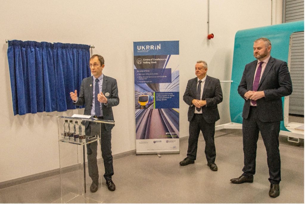
Following further consultation, industry expressed a desire to see more research into passenger comfort and into pantograph-catenary interaction. The Train Hi-fidelity Motion Simulator (THOMoS) and the Pantograph Huddersfield Experimental Rig (PANTHER) were born and, at a recent ceremony, the Minister of State for Transport, Andrew Stephenson, formally opened the facilities. The event also included a visit to a rig being developed for robotic bogie maintenance and guests received a preview of HAROLD 2.0.
THOMoS
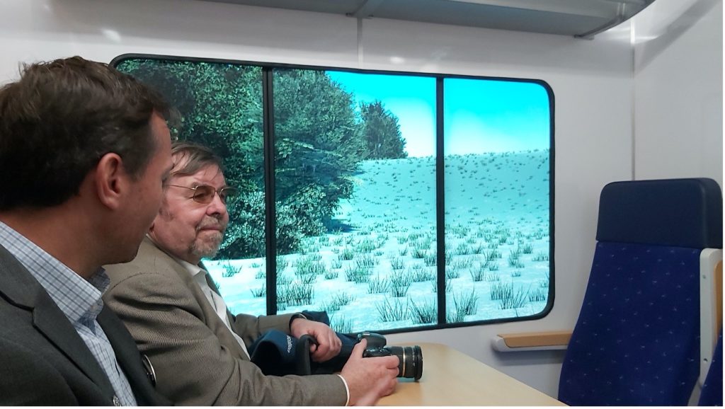
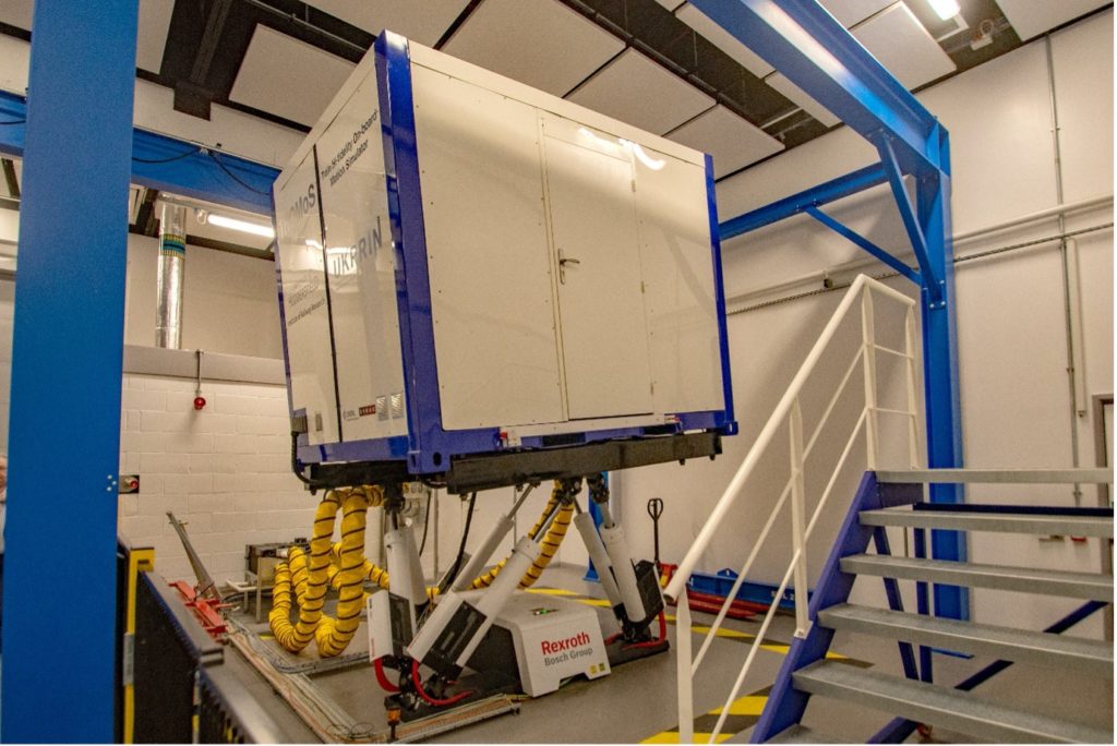
The Train Hi-fidelity Motion Simulator (THOMoS) is, in effect, a windowless 2.6 metre metal cube mounted on six large servo-electric actuators. On entering the box, one finds a single bay of eight seats arranged like a rail vehicle seat bay with LCD screens representing the windows. The actuators control the motion rather like a flight simulator or static fairground ride, albeit with less extreme movement.
The actuators are controlled by signals calculated from the suspension reaction of the vehicle type under test on any track. Real track geometry data obtained from Network Rail’s New Measurement Train is used with a model of the target vehicle as the inputs to Vampire vehicle dynamics simulation software. The output of Vampire is used as an input to the motion simulator control system.
The aim of the rig is to understand how customers react to the ride performance of a train or changes in track design alignment. When Rail Engineer had the opportunity to ‘travel’ in the simulator, it felt extremely realistic with ‘vehicle’ movement, sound, and the passage of external scenery. Track and suspension characteristics can be rapidly altered allowing researchers to observe volunteers’ reaction to varying ride quality.
For example, are occasional large movements due to discrete faults more disturbing than, say, a general slightly rough ride? Huddersfield’s Professor Paul Allen also explained that they are undertaking work to review the currently accepted limits for jerk rates at cant transitions and for varying degrees of cant deficiency.
The aim is, hopefully, to allow the limits to be relaxed and speeds to be increased. A line that would benefit from such a relaxation is the West Coast Main Line where non-tilting trains are limited to 110 mph compared with the tilting train limit of 125 mph. In 2023, non-tilting Hitachi AT300 trains will replace tilting Voyagers and studies are already under way to minimise the impact of non-tilting trains. Other applications include evaluating the effectiveness of changes to suspension or seat design, with the potential for designers to ‘ride’ on a train or route yet to be built.
PANTHER
PANTHER provides the opportunity to test pantograph performance and new pantograph technology without having to use expensive test trains/scarce test paths and without risk to the operational railway. The system can demonstrate the pantograph’s dynamic forces at simulated speeds up to 400 km/h enabling the analysis of existing or new designs. PANTHER’s electronic system controls the movement of the actuators which are capable of applying vertical excitations of up to 100 Hz and accelerations of up to 4 G onto the pantograph contact strips reproducing, in real time, the interaction with the catenary whilst in service.
Another actuator simulates catenary stagger with lateral movement of +/- 300 mm, maximum frequency of 1.5 Hz, and acceleration of up to 2.7 g. The pantograph under test is mounted on a platform with six degrees of freedom to replicate any train movements or vibration. There is a compressed air supply for the pantograph and there is an adjustable DC power supply and real time computer available for any active control systems. The demonstration clearly showed the difficult environment of the pantograph/catenary interface.
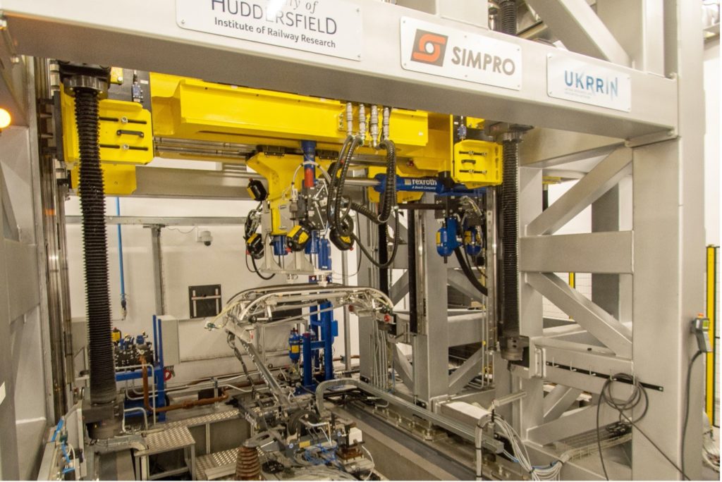

As an example of the tests that can be carried out on the rig more easily than on the railway, if PANTHER had been available during the time that the issues with electrifying under Steventon Bridge and over the adjacent level crossing on the Great Western route were identified (Rail Engineer March 2020), it would have been a lot easier to evaluate the impact on the system of more severe catenary gradients than are normally allowed. In particular, much less access to the railway for testing would have been required and there would have been much less risk.
The contact with the pantograph appeared to be made of some sort of plastic. When Rail Engineer queried why copper contact wire was not used, Dr Pedro Antunes, PANTHER’s ‘keeper’ advised: “The ‘contact patches’ set at the end of the actuators, are made of Teflon and have the shape of the contact wire machined in. Teflon is used to avoid wearing the pantograph contact strip when we want it not to. For example, we might want to perform tests that are repeatable, or consider a specific new or worn out contact strip shape.
“We can fabricate or machine other contact patches out of other materials, but the test rig also comes with a second accessory to use instead of the contact patches where a real contact wire can be installed. This accessory is attached to both ends of the high-performance hydraulic actuators and you can install any contact wire on it to make contact with the pantograph. The accessory also has a joint system that allows for the hydraulic actuator to be at different extensions and allow the contact wire to have some degree of pitch.
“Depending on a specific test, the type of contact patch or accessory are to be chosen to fit best the test’s objectives and considerations. For the demonstration presented, we decided to use the Teflon contact patches so the pantograph’s contact strips are not worn unnecessarily.”
(R) Minister of State, Department of Transport.
A planned task for PANTHER is to evaluate a new pantograph design. This is a collaboration between University of Huddersfield and University of Bristol, supported by Brecknell Willis and funded by Network Rail. Conventionally, pantographs respond to changes in catenary height using spring/mass/damper systems and there are issues maintaining the required vertical force at all times. This project intends to explore the benefits of using inerters (see Panel) instead of or in combination with conventional damping. Watch this space…
HAROLD 2.0
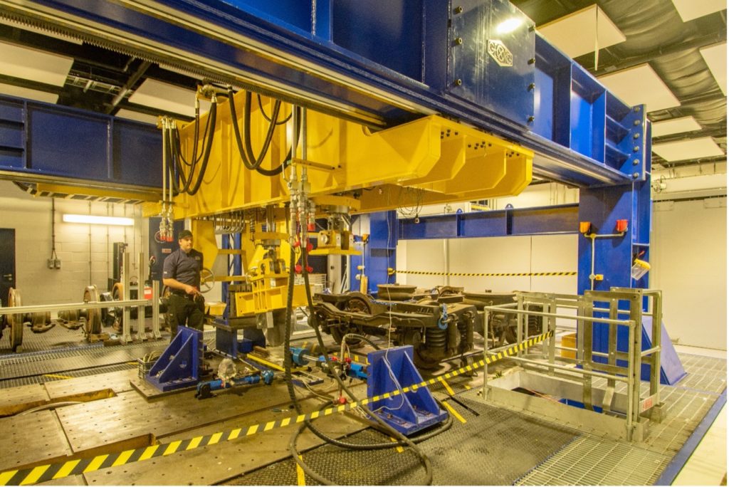
An upgrade is underway on IRR’s full-size railway bogie test rig costing £1 m and will include the integration of a real-time train braking performance model as well as the capability to prove novel hybrid drive and energy storage systems. HAROLD is the UK’s only full-size rig of its kind, featuring a motored rolling road that can drive a wheelset of a standard gauge bogie at speeds up to 200 km/h, exerting real-world forces via its hydraulic actuation system. Engineering consultant Ricardo is delivering the upgrade for IRR.
The upgrade will provide significant enhancements to the facility’s functionality, including a fully functional AC power bogie, comprising both friction and regenerative brake systems and complete traction package. Professor Paul Allen, Assistant Director of the IRR described the enhancements.
“In helping realise predictable and optimised traction and braking performance, HAROLD 2.0 enables testing and development of hybrid vehicle concepts and will support the railway industry in overcoming its wider decarbonisation and electrification challenges,” he said.
HAROLD 2.0 is part of a hardware-in-the-loop test method utilising on-train systems allowing next-generation wheel-slide protection (WSP), dynamic brake blending control, and traction components to be fully analysed. The test environment will have the ability to re-create traction and braking duty-cycles at speeds of up to 200 kph, under a range of wheel-rail adhesion conditions over a whole route to prove the systems prior to on-track trials.
The Director of the Institute of Railway Research, Professor Simon Iwnicki summarised the enhancements to braking as: hardware and software development; proving of next generation WSP systems; train brake blending controller optimisation (friction and electro-dynamic brakes); route-specific and brake duty-cycle testing to support vehicle acceptance and providing a stepping-stone between desktop/bench-tests and on-track trials.
He described the improvements to traction and energy systems as: wheel-slip and traction management system development, problem solving and proving; hybrid drivetrain and energy storage solution development and proving; real-time energy storage models; and whole-route energy cycle evaluation for proving hybrid drive solutions.
Professor Iwnicki said that HAROLD 2.0 is expected to be ready for operation by summer 2022.
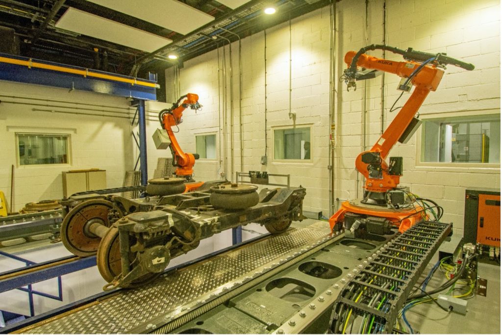
Robotic Train Maintenance
A new lab to investigate the use of robotics for train maintenance is almost complete, but not yet open. The facility comprised two industrial robots either side of a short section of standard gauge track over a maintenance pit – a representation of a typical train depot. The robots were able to move approximately 6 metres, although in a real depot, of course, this would be much longer to allow robots to maintain and inspect a whole unit of vehicles. A 1980s BR suburban style trailer bogie had been provided for initial investigations.
Rail Engineer was particularly impressed with both THOMoS and PANTHER and looks forward to hearing about the results of the research in the future.
What is an inerter?
Two components are typically used in a vehicle suspension:
» Springs, where the force in the spring is proportional to the displacement between the two ends
» Dampers, where the force in the damper is proportional to the velocity across the two ends
Suspension designers can select parameters for these two components to provide the best possible performance for specific requirements.
An inerter (not to be confused with an inverter) is a third component which provides a force proportional to the acceleration between its two ends. In its mechanical form it consists of a flywheel forced to rotate as the ends of the inerter move relative to each other. Using an inerter gives suspension designers more possibilities for optimising suspension performance.
Active components (such as electric or hydraulic actuators) or semi-active components (such as switchable or variable dampers) can be used to improve performance further, but they require complex controllers and a power supply.
With thanks to Professor Simon Iwnicki and his team for their assistance with this article.
Photo credits: David Shirres / Malcolm Dobell