

In spring 2021, cracks were found in yaw damper bracket mountings on some EMUs and DMUs operated by Northern Trains, and in yaw damper mountings and jacking points of Intercity Express Trains. These issues caused significant disruption and were therefore reported extensively in the media. Rail Engineer asked David Crawley, a specialist in this field, how asset operators, owners and engineers manage cracks.
Cracks are everywhere. Some matter, some don’t. How do we know which are which and what do we do about them?
There is no such thing as a perfectly homogenous defect-free material of any practical use. Even if there was, by the time it is joined to others, shaped, bent, drilled, crimped, welded, subjected to heat-induced loading and treated chemically, it would no longer be ‘perfect’. Competently manufactured items will, at best, contain only microscopic defects – hardly worthy of the name ‘crack’ – but they will seed the large-scale cracks that may emerge with use. Any design process must assume that a multiplicity of defects come naturally with the materials. This is, mostly, built into the applicable standards for design and manufacture, and QA inspection processes weed out the rest. So why do large-scale cracks still emerge?
However ‘perfect’ any manufactured item is, it can only be as good as the design process allows it to be. Loading is usually conservatively estimated over the intended life (measurements can deal only with a moment in time), but it is still an estimate. Usage can change, the environment can change, mistakes of analysis can be made, standards can be used inappropriately, materials can be selected incorrectly, residual loading from manufacturing processes can be inadequately accounted for, and testing and inspection can miss material defects and emerging problems.
These things are not all necessarily the ‘fault’ of anyone; who can criticise the Victorian engineers in the 1880s designing Hammersmith Bridge for failing to understand the amount of yet-to-be-invented motorised traffic it would carry, or failing to anticipate the increase in structural thermal loading due to human-induced global warming? Or that bearing failures over a century later would remain untreated until they caused real damage?
In the last 20 years, there has been a worldwide average of 6.3 bridges per year suffering structural failures. Even the iconic Cheesegrater (The Leadenhall Building) suffered a major failing in structural bolts in 2014, with all having to be replaced. After hundreds of years of design experience – with modern materials, standards and construction methods – this is a surprisingly high number and makes the point that the discovery of cracks in service is something to be expected and must therefore be accommodated in operating and maintenance processes.
Beyond fatigue
The two principal defences are inspection and maintenance, to detect defects and to prevent them. Both are matters of judgement and should, ideally, be constantly revised according to any evidence emerging in their use. Mistakes can be made, but even if they are not, aficionados of fracture mechanics know that there is another problem.
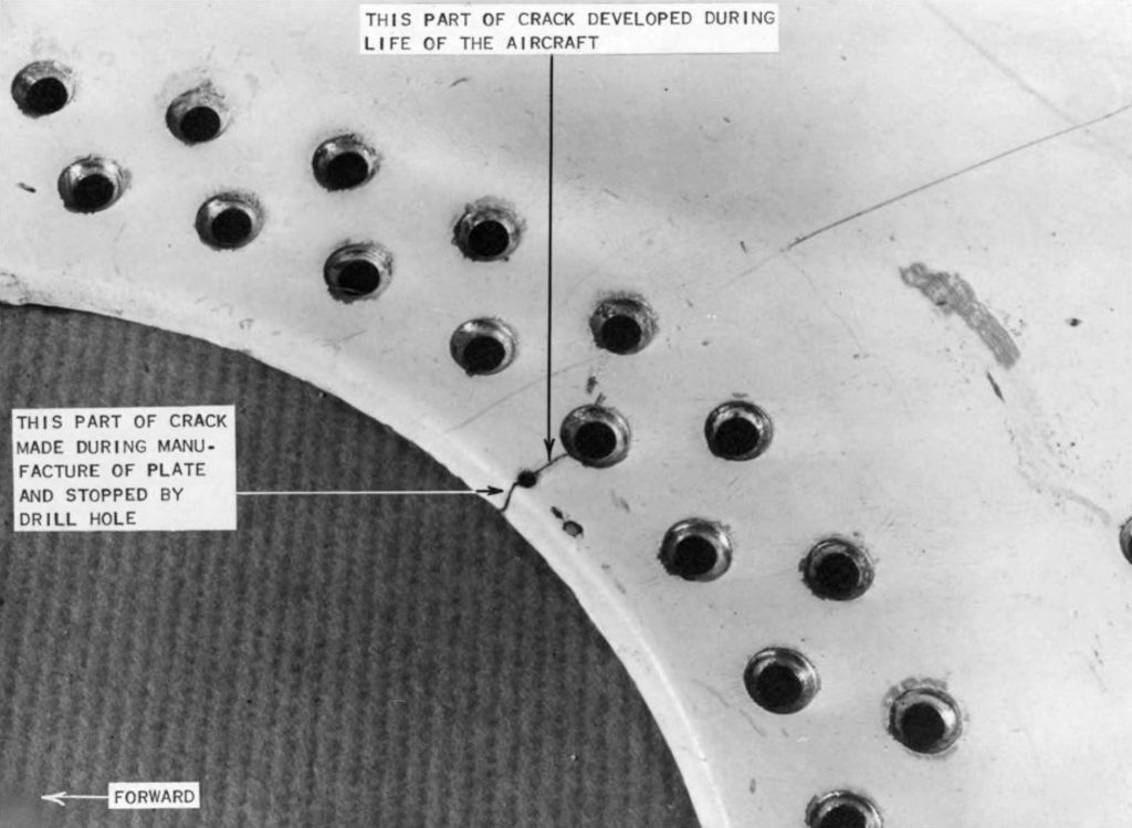
The process by which microscopic defects grow into detectable cracks under cyclic loading if it is high enough – sometimes missed in the design process – is well understood and termed ‘fatigue’. Less well appreciated is that once those cracks reach a certain critical length, they can grow catastrophically if the conditions are right. A high tensile stress field in combination with large enough cracks can cause a structure to shatter like glass; the Comet airliners were among the first visible examples of this phenomenon and two London Underground rolling stock fleets have had localised, and contained, examples. If a design is not properly understood, such behaviour remains a risk.
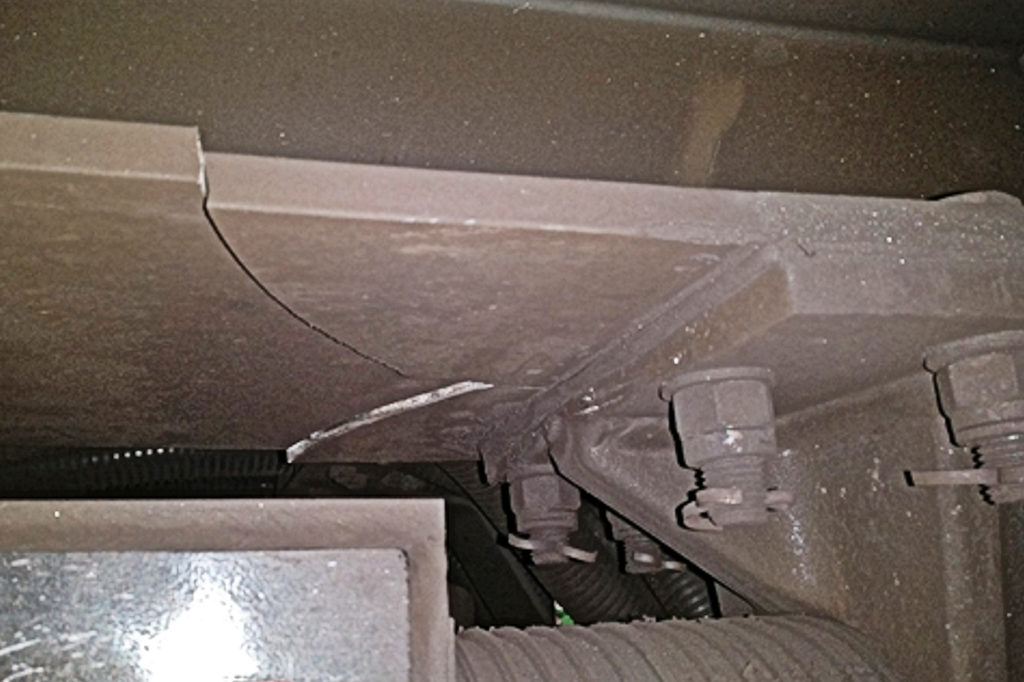
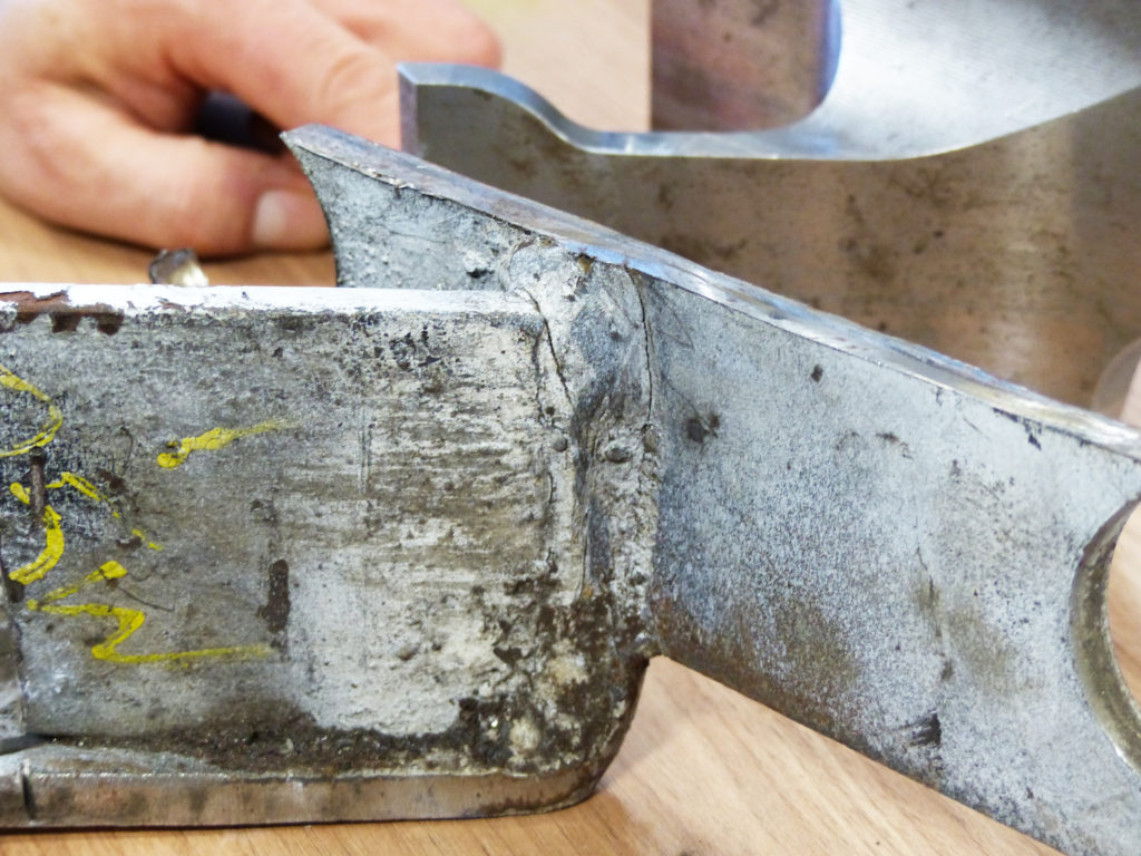
The now-common use of aluminium rather than steel for rail vehicles is driven by weight and consequent energy saving, leading to a reduction in whole-life costs. It is possible, for a given duty, to build a lighter structure in aluminium than steel, but great attention must be paid to highly-stressed areas such as bogie/car-body interfaces, door openings, buffing and draw-gear structures, and lifting points. Close attention must be paid to the characteristics of aluminium having one-third the strength of steel and more sensitive fatigue characteristics. The greater difficulty in welding aluminium must also be taken into account in design details to ensure that premature failures do not occur.
Design details can make or break a design. Sudden changes of section, or welding, in highly-stressed areas don’t work well.
Checks and balances
For railways, there are some examples of things being done very well; axles and rails both receive a high degree of attention in design, inspection and maintenance as they represent a true opportunity for single-point failure leading to high risk of loss of life. For vehicles, it is usually the case that a crack that is detected could only become dangerous if left untreated. Service suspensions to maintain safety risk acceptably low while solutions are found are not the norm.
There is a well-established routine applied when a crack is discovered. How prevalent in the fleet is the defect? Cracks emerge across a fleet – one by one – according to some distribution of probability and, if the defect is one of design rather than of some externally applied random events, they are often normally distributed in growth. Many found on the first inspection indicates rapid growth as more frequently applied inspection regimes would otherwise have detected the first few as they emerged.
This knowledge contributes to the solution. A rapid check of the entire fleet would follow after discovery of a crack if it were in any location which could cause a serious failure – a primary load-bearing member, with no other load path being available, or a location which, on crack extension, could cause gauge fouling or loss of equipment. Any of these could be the root cause of a derailment at speed with significant risk of loss of life.
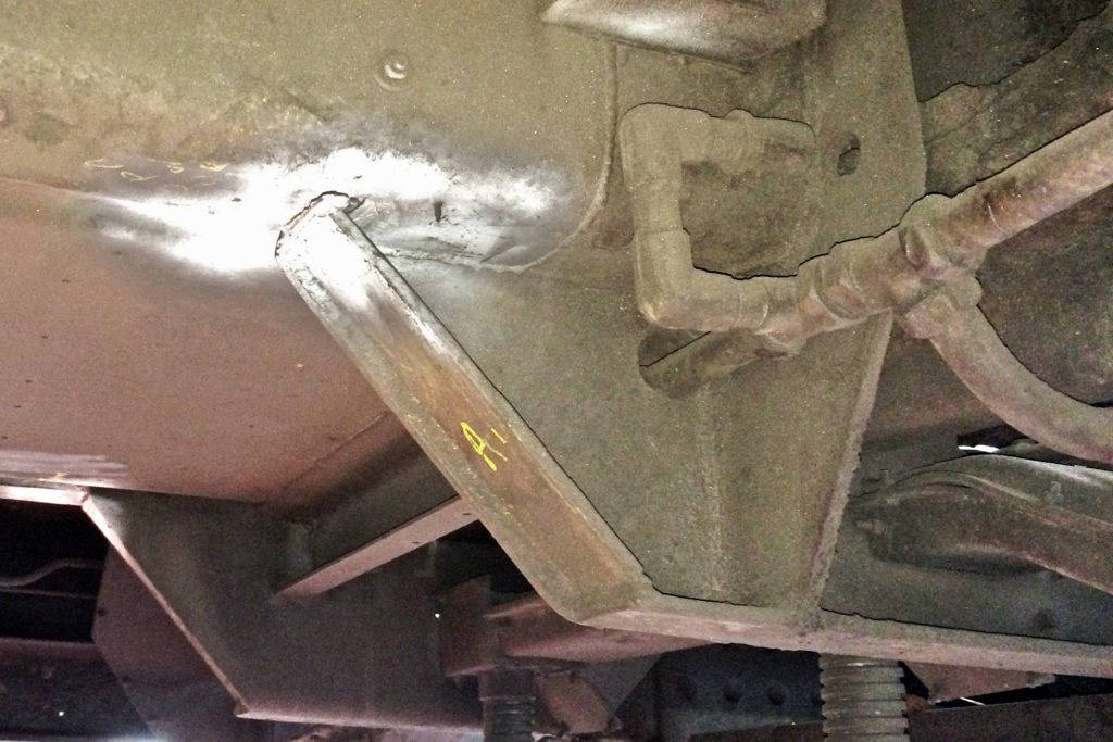
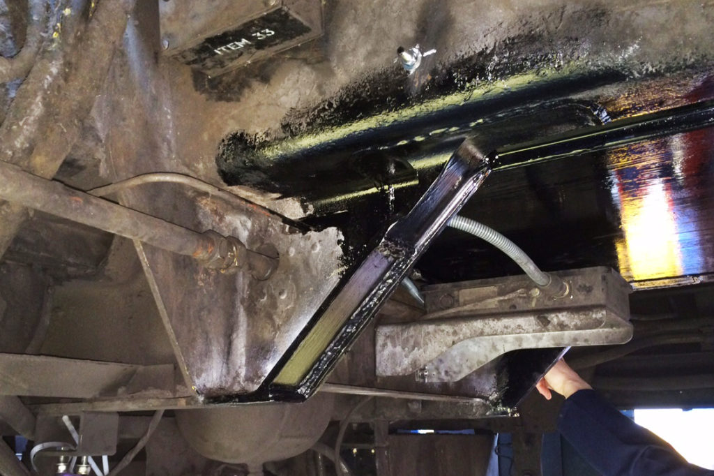
Any vehicles with such defects would be quarantined. Others may be allowed into service with an enhanced inspection regime applied if it could be shown that the rate of crack extension is slow enough to allow a crack to be found before its length became unacceptably great. No permanent solution could be applied until either the reason for the emergence of the defect was understood or it was rendered irrelevant by some other change. Typical of the latter is the application of secondary supports to equipment at risk; if the primary support fails then the secondary support would temporarily take over the duty. This is only a short-term solution until a permanent one is found, but it would allow some resumption of service until that point.
Determining root cause
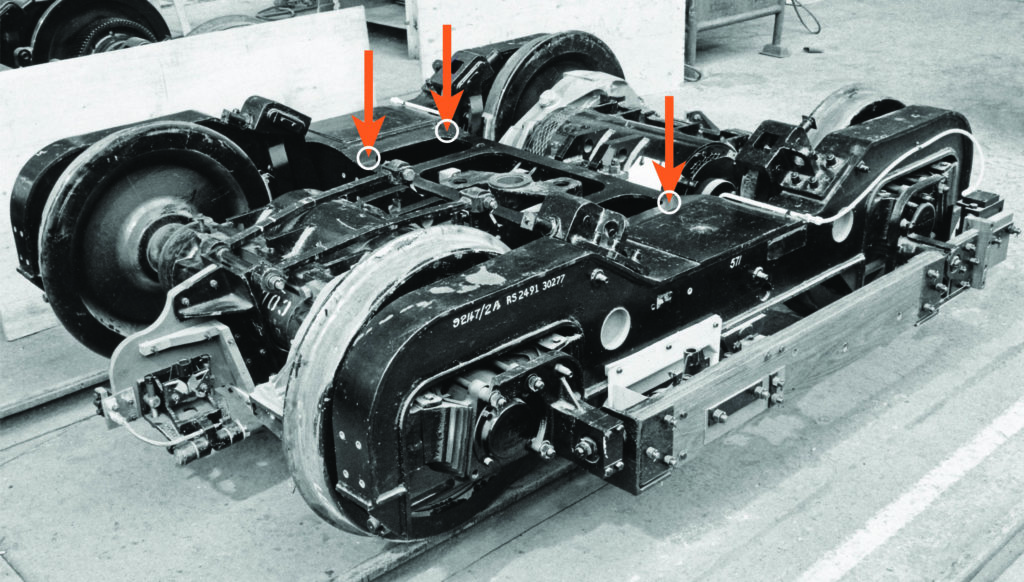
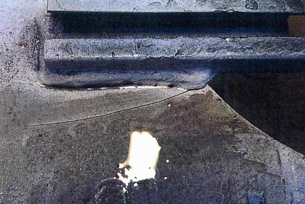
Occasionally, the existence of a crack indicates the relief of significant residual stresses, often from the build technique employed. In the case of the now-defunct 1983 stock running on the London Underground’s Jubilee Line, a series of 200mm long cracks were discovered on almost all bogie transoms. They were there from the first few weeks in service so had certainly grown very rapidly. However, no further movement was noted as the residual stresses which had contributed to the cracking had been relieved and the cracks were so long that they changed the gross torsional stiffness of the bogie beneficially. A simple bolted patch repair was employed which lasted without incident until the fleet was scrapped. This was a failure of both design and manufacture, with changes of section at high-stress locations and high residual stresses from the build methodology.
Some cracks simply stop growing because they are moving into a compressive stress field. It is possible to initiate a crack in a component under cyclic net compressive loading if it experiences plastic deformation locally to a stress-raiser like a sharp corner. When the load is removed, there is a range of relative tensile stress experienced on the ‘rebound’ which causes the crack. As it grows, the relative tensile stress range reduces because the crack has moved beyond the stress-raising feature and into a net compressive stress field. This is a defect that might be associated with the stop brackets for trams’ magnetic track brakes and they usually require no repair.
Temporary solutions, particularly those employing enhanced inspection, cannot be employed indefinitely, not least because natural crack growth would soon keep the whole fleet out of service. The hunt for a permanent solution can be difficult as it demands a good understanding of the root cause of the failure. That requires clear evidence of the actual loading environment and the design details. Nobody can claim to have fixed a problem if they don’t know why it happened. This is the reason for what can seem like extended delays before full-service resumes after a major defect is found.
Another temporary solution that usually doesn’t work is drilling a hole at the end of the crack which is supposed to reduce stress by ‘blunting’ the crack tip to stop it growing. There are three problems – finding the end of the crack reliably enough to know that it isn’t still there further on in the path, ensuring that the stress field isn’t so great that a new crack will just initiate again inside the hole after a brief pause and continue, or, worse, in the case of the 1983 bogies example, guarantee that the crack reaches a critical length by extending it before it would have reached that length naturally, but more slowly. Removing strength by drilling rather than replacing lost strength is not a reliable strategy unless the crack is caught at a very short length and the stress is low enough anyway not to reinitiate a crack.
Drawing board
How to repair a crack? The most ‘obvious’ remedies are no remedies at all, for example, welding the crack. If the crack happened in parent metal, then the repair would certainly be weaker than the original which had already proved to be substandard. If the crack happened in weld material, then the repair may fail again even more rapidly. All this assumes that welding would even be possible; some aluminium alloys require very specialised techniques to be used.
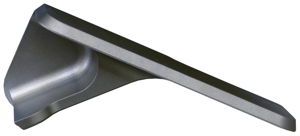
Valid permanent solutions usually involve some element of redesign and have some combination of load reduction, possibly through partial diversion of load through additional load paths, or possibly through change of use, the use of details that are less prone to crack initiation, or the use of different materials or fastening techniques. Additional monitoring may also be employed.
These techniques are commonly applied to rolling stock, but apply equally to other structures such as bridges. For example, Highways England standard CS 470, Management of sub-standard highway structures, has the concept of ‘Immediate Risk Structure’ and the management techniques follow the same principles that apply to rail vehicles. The next category is that of ‘Substandard Structure’ – in which the risk is less immediate – and monitoring and load reduction can be employed safely to allow the structure to remain in service.
All of this can be summarised as: find and quarantine defects that are a threat, monitor the rest well enough to ensure they don’t become a problem in service, understand the root cause of the defects and use that information to develop a permanent solution which will usually require some redesign, then change the inspection and maintenance regime to reflect the new reality.
David Crawley joined London Underground in 1983 following work in British Aerospace on airframe design. He developed the processes and procedures for managing cracked components on London Underground’s trains, investigating and designing repairs for many such examples. Later, he held several senior management roles in LU and the Metronet public-private partnership consortium before founding and leading engineering consultancy Xanta Limited.