

Articles on electrification invariably focus on 25kV overhead systems or indeed the modern-day 50kV auto-transformer variant. The safety procedures that go with these are well documented and accidents are thankfully very rare. We must remember however that a significant percentage of the UK electrified railway uses live conductor rails positioned on the outside of one or other of the running rails. These carry 750V DC and are capable of delivering many thousands of amps.
Whilst the majority of this third rail network is on the ex-Southern region, we must not forget Merseyrail Electrics and the Euston-Watford DC lines. There is also, of course, the London Underground network using the fourth rail configuration plus the Docklands Light Railway with at least the electric pick up being on the underside.
Can you imagine what the Health & Safety Executive would pronounce if you were to go to them with the third rail system as a new invention and ask for safety approval? An openly exposed high-voltage rail at shin height without any form of protection would be laughed out of court. Yet this is a day-to-day reality for many trackside workers who have to maintain the permanent way, under-track cable crossings and such like. Is it any wonder that despite the rules for access and taking of isolations, accidents do occur from time-to-time with very serious consequences.
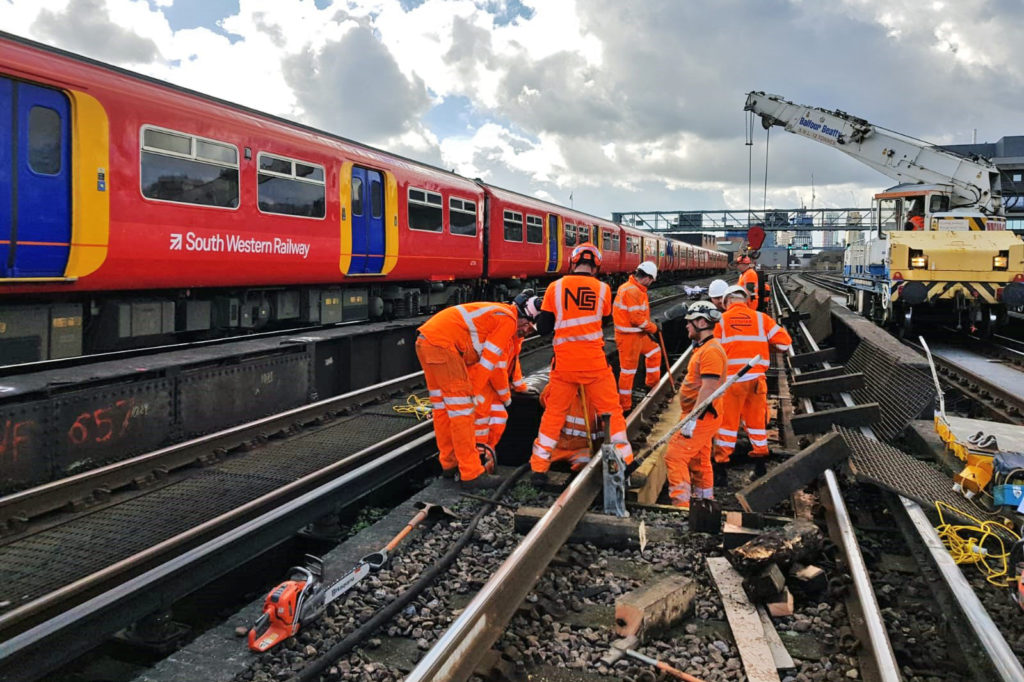
My own time on the Southern Region in the 1980s occasionally meant going on the track and a very big step was taken to get over the live rail. If this is something you have to do on a daily basis, the old adage of familiarity breeds contempt might just kick in.
For signal engineers, the third rail is an ever-present reality. A talk was given recently to the IRSE London & SE section by Neil Clegg, who has a background in Electrification & Plant engineering, to tell of a safety improvement that is making trackside work less vulnerable to contact with the live rail.
Existing procedures
Routine track maintenance is often carried out with the third rail still live. Rules make clear what types of work staff can or cannot do, the safeguards to be implemented and extreme care that must be taken. For any significant work, an isolation – switching off the current – must be made. This requires the cooperation of the staff on site and the Electrical Control Operator (ECO).
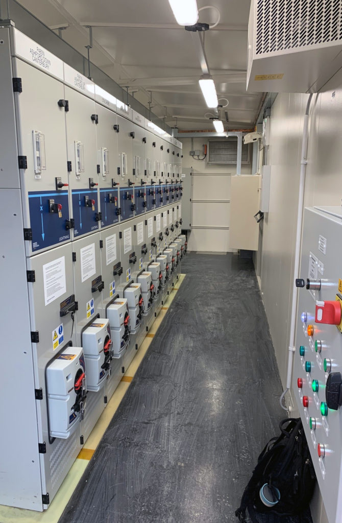
To know what is involved, we must first understand the basic layout of a third rail power arrangement. From the national grid 400kV or 132kV transmission lines, 33kV or 11kV power cables are installed into lineside substations. Sometimes these cables are part of the railway infrastructure and run in trackside troughing routes. The substations are typically 3-4 miles apart and incorporate a transformer rectifier to obtain the 750V DC. Circuit breakers protect this supply before the connection is made to the third rail and will open when fault conditions occur, for example a short circuit between the live rail and the running rail.
Bear in mind that a DC train needs a lot of amps when accelerating from a station stop and the system has to be capable of delivering that power. Between the substations are Track Paralleling Huts (TPH) which enable the third rail to be sectioned to increase the track voltage regulation between substations, i.e. keep it within the standards prescribed for the trains.
To arrange a track possession, a power isolation is required and this is achieved by a two-way procedure between the Person in Charge of the Possession (PICOP) and the ECO. The operator will open the breakers for the section required whereupon the Engineering Supervisor (ES) gets authority to instruct staff to test locally with a Live Line Tester (LLT) where straps will be applied; then a short circuit bar is placed between the third rail and adjacent running rail to protect against any inadvertent switch-on. Short circuit (SC) straps are then applied and the bar can be removed thereafter. All of this takes time and is backed up by communication procedures and logged on the appropriate forms.
Incidents do arise and can be caused by:
- the SC straps being applied before the short circuit bar is in position
- the SC straps being applied at the wrong location
- no live voltage test being carried out
- the rails not being brushed to ensure a good connection
- the SC straps being applied but not tightened.
The Negative Short Circuit Device
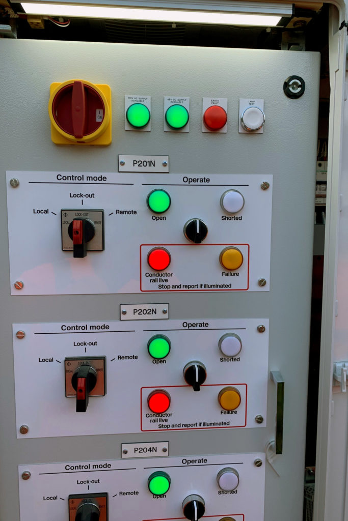
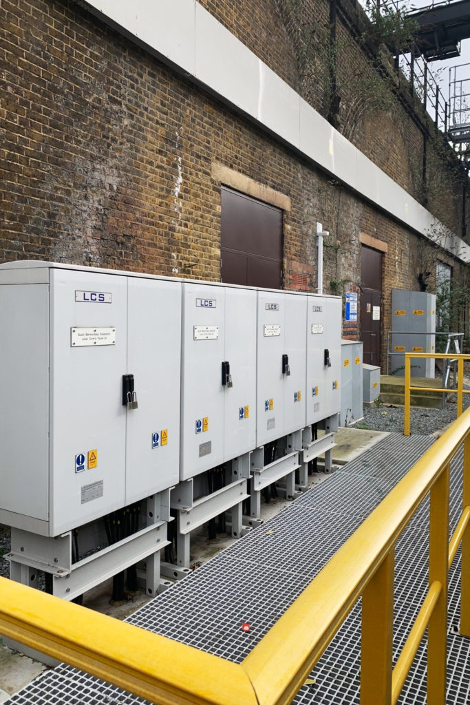
To overcome this somewhat clumsy arrangement, a new process involving a Negative Short Circuit Device (NSCD) is being introduced to effectively replace the short circuit straps. They are controlled from a Local Control Panel (LCP) which are situated in green zone areas, predominantly at access points. The LCPs control the NSCDs which are short circuit switches wired between the track side of the DC circuit breaker and the negative bus bar at substations and TPHs. The LCP enables the PICOP to make an isolation from a position of safety and not needing to go on or near the line.
An electrical interlock prevents the NSCD from being operated before the ECO opens the power feed circuit breaker. The NSCD equipment is housed in a cabinet comprising the switching components that are wired in parallel with the normal feed to the rail, which then connects via the negative bus bar to complete the short circuit. The LCP includes a toggle switch on the front of the cabinet showing a green light when the NSCD is open, a red light when the conductor rail is live and a yellow light to indicate any lamp failure. When the NSCD is operated, a white ‘shorted’ lamp is illuminated. The toggle switches are controlled by a local lockout/remote selector switch which is secured by a lock and key. Good labelling is an essential part of the system to ensure there is no confusion as to the site or live rails being protected.
To enable the NSCDs to protect two simultaneous possessions and associated isolations, two key boxes are installed – red and yellow – that allow a double-locking arrangement so as to protect inadvertent switch-on if one of the isolations is no longer required.
Two types of NSCD are available:
B4 – an NSCD is installed for an electrical section. It is wired in parallel with the normal feeds to the rail from either a substation or a TPH
B5 – only one NSCD is installed between the positive and negative bus bars at substations. Currently the safety case is being assessed on the requirement to provide B5 NSCDs at TPHs.
The NSCDs are manufactured either by HSS (Hawker Siddeley Switchgear under the Brush parent company banner) or by LCS (L C Switchgear).
Advantages and actions required
All NSCDs are operated from the LCP which is interlocked with the circuit breakers. It is a quick operation and they negate all risks associated with the placement of SC straps. These can still be applied at the extremities of an isolation if additional assurance is thought to be required.
The procedure is as follows:
- the PICOP takes the possession and makes a request to the ECO
- the ECO opens the applicable circuit breakers
- the ECO instructs the PICOP to close the NSCD
- the PICOP informs the Engineering Supervisor of the NSCD status
- work can commence.
At the end of the possession, the reverse procedure is followed, ending with the PICOP informing the ECO that all NSCDs are now open; thereafter, the circuit breakers can then be closed to restore the traction current.
Should a NSCD fail to open at the end of an isolation, emergency procedures are in place to re-energise the circuit breakers so that power can be restored to the trains. At present, the ECO does not have remote monitoring of the NSCDs so a verbal assurance is required. It is the intention that with the rollout of the SCADA programme, this facility will be provided to add another safeguard.
Implementation
To date, the London-Brighton main line and branches have been equipped with NSCDs, along with parts of the Kent lines. The provision of NSCDs on the South-West lines is in the CP6 programme. Rollout across the whole of the ex-Southern Region should be completed by the mid-2020s. It is expected that the Merseyrail and Euston-Watford lines will be similarly equipped in due course.
There will always be risks with the safety of staff in third rail traction areas so NSCDs are not the ultimate protection. They are however a big step forward in improving safety procedures for this type of electrification.